
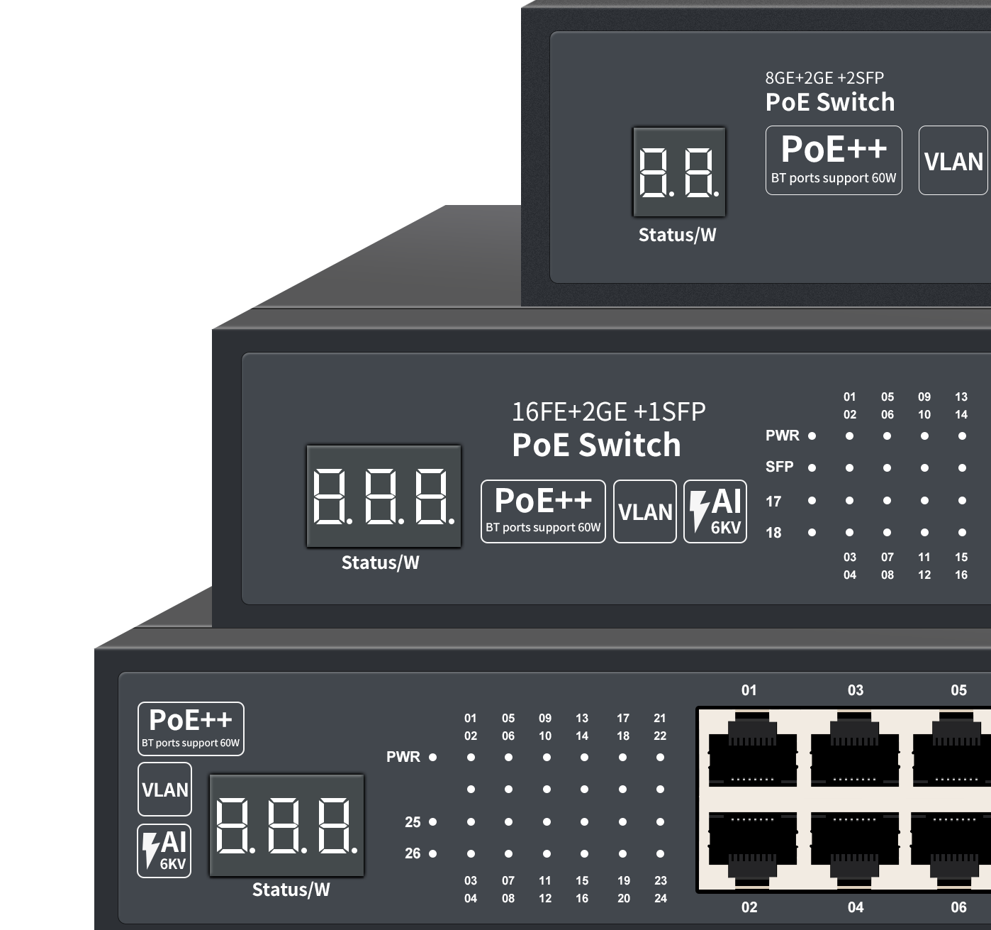

Why Most Smart Building Network Projects Run Into Trouble Before Commissioning
Talk to any weak current project manager who has delivered a commercial building automation project, and you will hear the same complaints: the network backbone was designed in isolation from the BAS (Building Automation System), the PoE budget was calculated on paper but never validated under real concurrent load, and the integrator ended up running three separate management portals for CCTV, access control, and the building management system.
That fragmentation is not a small inconvenience. It directly inflates commissioning time, creates handoff gaps between sub-contractors, and leaves the building owner with a network that facility staff cannot maintain without calling in specialists every few months.
This guide breaks down how to design, specify, and deploy a converged smart building network infrastructure — one that carries BAS control signals, IP surveillance, VoIP, digital signage, access control, and energy monitoring over a single managed network fabric. All architecture recommendations here are grounded in IEEE 802.3bt/at/af PoE standards, TIA/EIA-568 structured cabling specifications, and Wanglink’s engineering lab data drawn from 800+ simulated full-building deployment projects and 1,200+ real-world weak current installations globally.
If you are sourcing hardware, evaluating solution architecture, or pricing a project bid right now, the sections below are written for exactly that decision stage.
Scope and Applicable Project Types
This solution is designed for:
- Commercial office towers and Grade A business parks (15,000 m² and above)
- Government and public administration buildings with mixed-use floors
- Multi-tenant industrial parks requiring converged IT/OT network management
- University campuses and hospital facilities with concurrent BAS + surveillance loads
- WISP-served building complexes requiring backbone WAN integration with in-building LAN
The smart building network solution described here covers eight application subsystems: Building Automation (BAS/楼控), Energy Management, IP Video Surveillance, Public Address (PA), Multimedia Conferencing, Digital Signage, Property Management Platform, and One-Card Access Control. All subsystems converge on a unified IP network fabric rather than running independent cabling plants.
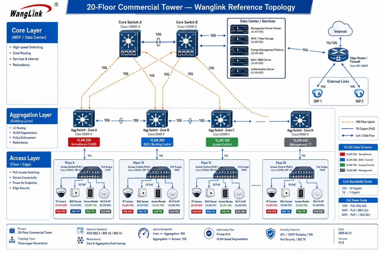
Network Architecture Design: Three-Layer Converged Fabric
Layer 1 — Access Layer (Floor-Level PoE Switching)
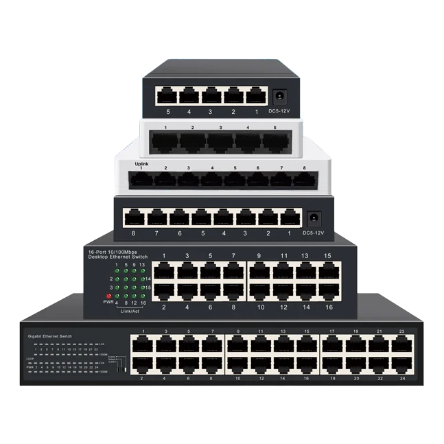
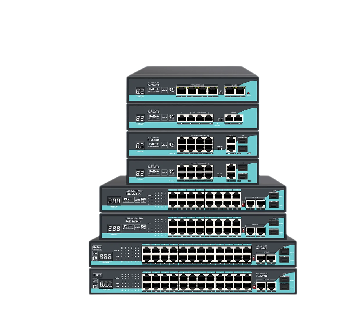
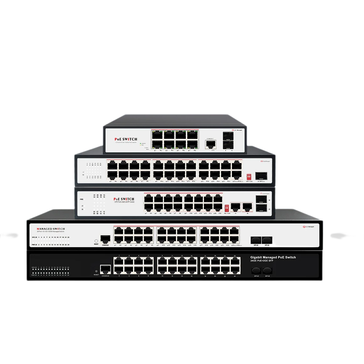
Every floor’s devices — IP cameras, access control readers, BAS sensors, VoIP handsets, wireless APs — terminate at access-layer PoE switches. For a standard commercial floor plate (800–1,200 m²), budget for 24–48 PoE+ ports per floor switch, with IEEE 802.3at (30 W per port) as the baseline and IEEE 802.3bt (90 W per port) where PTZ cameras or high-power APs are in scope.
Key spec checkpoints at access layer:
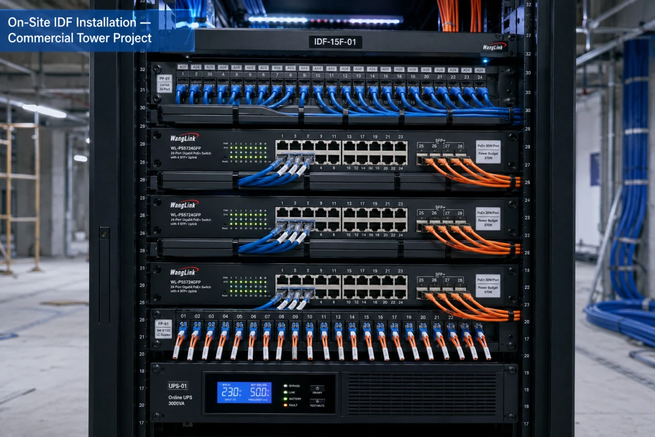
- Total PoE power budget per switch: minimum 370 W for 24-port under 60–70% concurrent load
- Backplane switching capacity: ≥ 48 Gbps to avoid upstream bottleneck
- Uplink: dual SFP+ 10G fiber uplinks to aggregation layer
- VLAN segmentation: minimum 4 VLANs (surveillance, BAS, access control, management)
Layer 2 — Aggregation Layer (Building-Level L3 Switching)
Aggregation switches sit in the main IDF (Intermediate Distribution Frame) per building zone, handling inter-VLAN routing, QoS policy enforcement, and uplink to core. For a 20-floor commercial tower, a pair of stackable L3 switches with ≥ 400 Gbps switching capacity per unit, running OSPF or static routing between VLANs, is standard practice.
At this layer, QoS markings must be configured deliberately: BAS control traffic (latency-sensitive, low bandwidth) gets strict priority queuing (DSCP EF); surveillance streams (high bandwidth, moderate latency tolerance) get DSCP AF41; general office traffic gets best-effort. Skipping QoS at aggregation is the single most common root cause of BAS response lag complaints post-handover.
Layer 3 — Core Layer + Data Center / Management Platform
The core switches (or a collapsed core/aggregation design for buildings under 10 floors) connect to the building’s main MDF (Main Distribution Frame), where the integrated management platform server, NVR clusters, energy management servers, and WAN uplink (ISP fiber or WISP backhaul) terminate.
The management platform runs single sign-on (SSO) across all subsystems — one dashboard, role-based access control for building operators, security staff, and facility managers. This is where the data fusion layer aggregates real-time feeds from BAS, energy meters, surveillance, and access control into a unified operations view.
Hardware Specification and Sourcing: What the Bill of Materials Actually Needs
PoE Switch Selection — Where Projects Overestimate Budget and Underestimate Load
The most frequent BOM error Wanglink’s pre-sales engineers see in incoming project RFQs: the client specifies 24-port PoE switches rated at 370 W total power budget, then populates every port with a 25.5 W PoE+ IP camera. That is 612 W demanded against a 370 W budget — the switch enters power-capping mode, cameras start dropping frames, and the client blames the NVR software.
The field rule: calculate actual concurrent load at 75–80% port utilization, then add 20% headroom. For a 24-port deployment with 18 active PoE+ devices at 25.5 W each, actual demand is 459 W. Minimum switch PoE budget: 550 W. Wanglink’s WL-S2024PoE-BT series delivers 600 W total budget in a 1U form factor, validated under 100% concurrent load in our engineering lab (Wanglink Engineering Lab Full-Load Test Report, Q3 2025, n=120 units).
Fiber Backbone Cabling — TIA/EIA-568 Compliance Is Not Optional
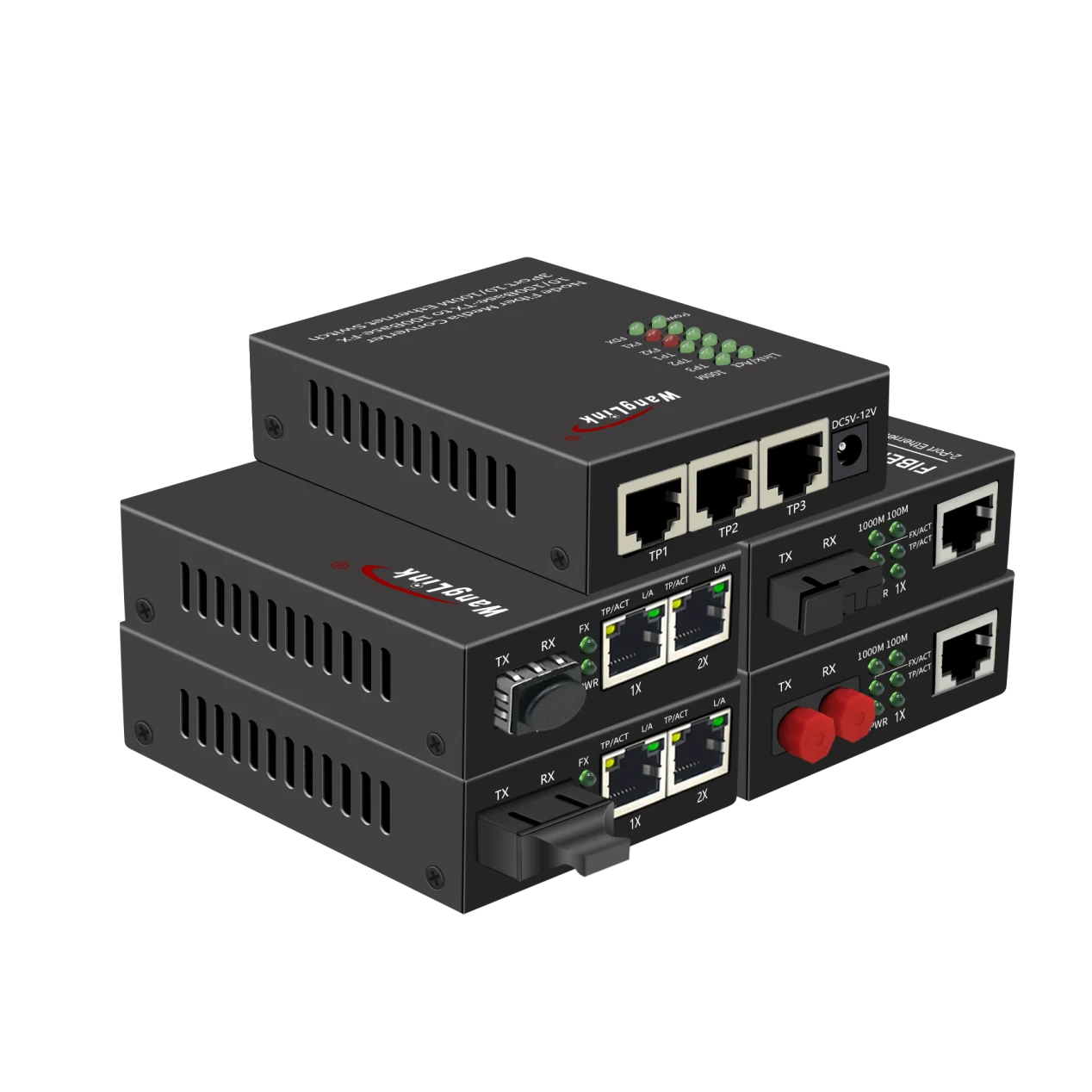
Between floors (vertical backbone) and between MDF/IDF (horizontal inter-closet), use OS2 single-mode fiber for runs over 100 m, OM4 multimode for runs under 100 m where 10G SFP+ is the uplink standard. TIA/EIA-568-C.3 specifies insertion loss limits of ≤ 0.5 dB per connector and ≤ 1.0 dB per splice — these limits must be measured and documented at acceptance testing, not assumed.
Wireless Access Points — Positioning for High-Density BAS + Office Co-Existence
In buildings where the BAS uses Zigbee or Z-Wave sensors alongside standard Wi-Fi (2.4 GHz / 5 GHz), RF interference planning is mandatory. Position APs on a 15–20 m center-to-center grid for standard office floors, tighten to 10–12 m for conference rooms or lobbies with high concurrent user density. Each AP uplink requires PoE+ (802.3at) minimum; Wi-Fi 6 APs with dual-radio design typically draw 22–25 W under load.
Subsystem Integration: Eight Systems, One Network Fabric
IP Video Surveillance Integration
Surveillance is typically the highest-bandwidth subsystem in a smart building deployment. A 2 MP H.265 IP camera at 1080P/25fps generates approximately 2–4 Mbps per stream. A 20-floor building with 8 cameras per floor (160 cameras total) produces a sustained aggregate stream of 320–640 Mbps toward the NVR cluster. Size your aggregation uplinks and NVR-side NICs accordingly — 10G fiber uplinks at aggregation are not over-engineering; they are the correct call.
The surveillance VLAN should be isolated from general office traffic with ACLs preventing cross-VLAN access except from the management server. Storage sizing: 90-day retention at H.265 for 160 cameras at 3 Mbps average = approximately 466 TB raw. Plan NVR expansion slots from day one.
Building Automation System (BAS) Network Integration
BAS controllers (handling HVAC, elevator monitoring, chilled water systems, lighting control) communicate over BACnet/IP or Modbus TCP, both of which run natively over the IP network fabric. Latency requirements for BAS control loops are tight: end-to-end command response must stay under 100 ms for HVAC setpoint changes, and under 50 ms for fire/emergency alarm relay signals.
Achieving this means BAS traffic gets strict priority (DSCP EF, queue weight ≥ 40%) at every network hop. In Wanglink’s lab testing across 800+ simulated building control scenarios, BAS command latency on a properly QoS-configured three-layer fabric averaged 8–12 ms end-to-end, well within ASHRAE Guideline 36 control loop response requirements (Wanglink Engineering Lab Simulation Data, Q4 2025).
Access Control and One-Card System
Access control readers and door controllers connect via PoE (IEEE 802.3af, 15.4 W typical) to the access-layer switches. The one-card system integrates with parking management, elevator floor control, and visitor management over the same IP fabric. NFC and RFID reader data flows to the access control server via dedicated VLAN, with SNMP traps forwarded to the central management platform for real-time door status monitoring.
Energy Management System Integration
Smart meters, sub-metering devices, and power quality analyzers communicate via Modbus TCP or DLMS/COSEM protocol to the energy management server. Real-time data collection intervals of 15 minutes or less are achievable on a stable LAN fabric with sub-millisecond jitter. The energy platform generates visualized dashboards showing per-floor, per-circuit consumption breakdowns — the kind of data facility managers need to meet ISO 50001 energy management system requirements.
Deployment Workflow: From Cable Pull to System Handover
Phase 1 — Structured Cabling Installation (Weeks 1–3)
Start with backbone fiber: pull OS2 single-mode between MDF and each IDF, test with OTDR, document insertion loss per TIA-568-C.3 limits before any active equipment goes in. Horizontal copper runs (Cat6A minimum for PoE+ reliability and thermal performance) from IDF to each device outlet, tested with a Fluke DTX or equivalent — channel length ≤ 90 m per TIA-568 specification.
Phase 2 — Active Equipment Mounting and Layer 2 Bring-Up (Weeks 3–5)
Rack and power up access-layer PoE switches floor by floor. Baseline configuration: VLAN trunk configuration, STP (Rapid PVST+ or MSTP), PoE power-per-port limits set to 30 W (PoE+) or 90 W (PoE bt) as per device class, uplink fiber connections tested for signal loss. Confirm switch management reachability from MDF before proceeding to device connection.
Phase 3 — Subsystem Device Commissioning (Weeks 5–9)
Connect and commission subsystems in this recommended sequence: IP cameras first (highest bandwidth, easiest to stress-test the network), then access control, then BAS controllers, then PA/signage endpoints. Running surveillance traffic first stress-tests the network fabric before lower-bandwidth BAS traffic is added. Any latent cabling or switch configuration issues surface here, not at final acceptance.
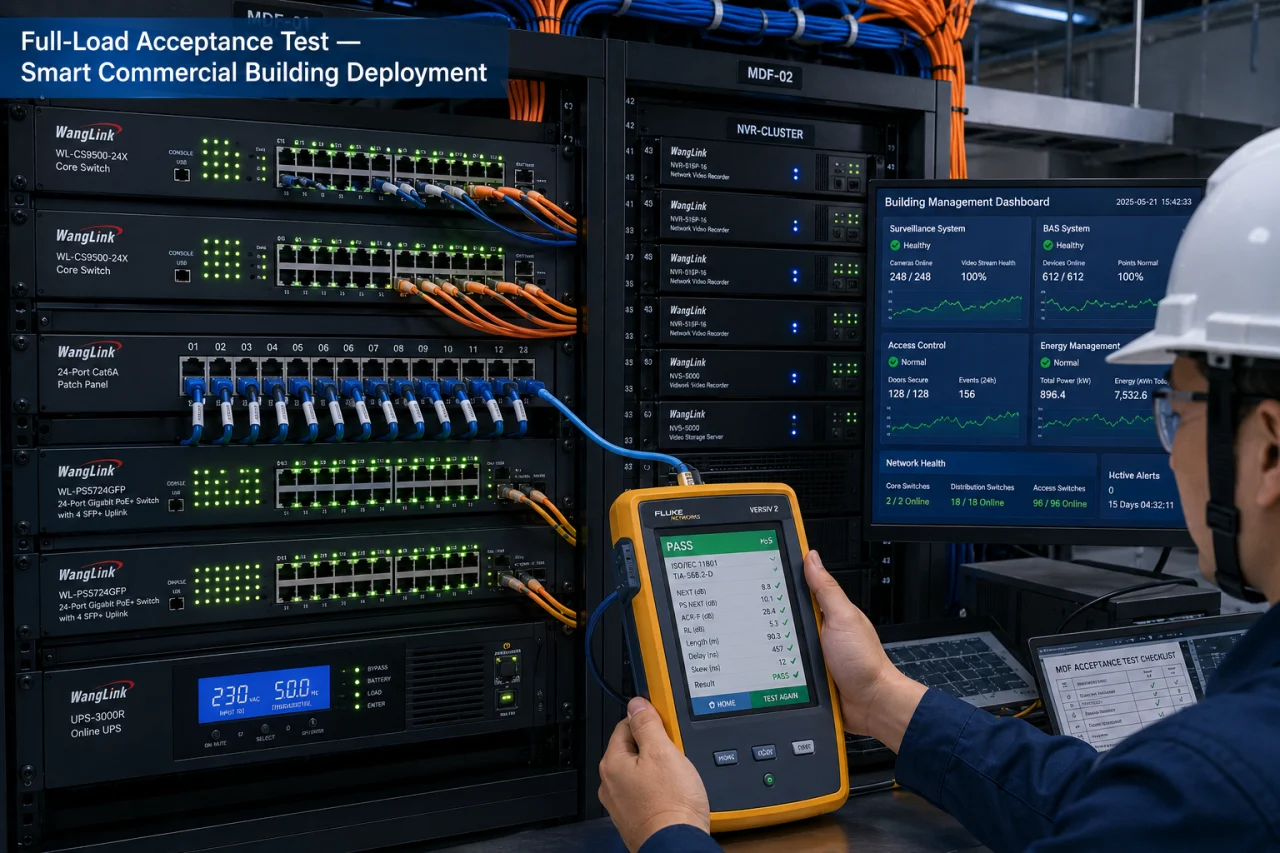
Phase 4 — Integrated Platform Configuration and Full-Load Testing (Weeks 9–11)
Bring up the unified management platform — SSO configuration, role-based access control, cross-system alarm linkage rules (e.g., access control breach triggers surveillance camera preset movement and PA announcement). Full concurrent load test: all cameras streaming, BAS polling active, access control traffic running, energy meters reporting. Target metrics: network packet loss < 0.01%, BAS command latency < 50 ms, surveillance stream uptime 99.9% over 72-hour test window.
Phase 5 — Acceptance Testing and Handover Documentation (Week 12)
Formal acceptance deliverables: OTDR test reports for all fiber runs, copper channel test reports (Fluke), PoE power budget worksheet per floor, VLAN and routing configuration as-built, full-load test log, NVR storage capacity verification, and a 12-month maintenance schedule. Wanglink provides project commissioning support and full documentation templates as part of the solution package.
Total Cost of Ownership (TCO) Analysis
Where Fragmented Solutions Cost More Than They Save
Traditional smart building deployments — where CCTV, BAS, access control, and PA each run on separate network infrastructure — typically result in:
- 3–4 separate cabling plants, multiplying materials and labor cost
- Multiple management portals requiring dedicated operator training
- Cross-system alarm linkage requiring expensive middleware integration
- Higher fault isolation time because no single team owns the full network
A converged IP fabric eliminates redundant cabling, consolidates management, and reduces the skills-set fragmentation problem. The TCO difference is measurable.
Solution TCO Comparison: Traditional Fragmented vs. Wanglink Converged Smart Building Network
| Metric | Traditional Fragmented Solution | Wanglink Converged Solution | Improvement |
|---|---|---|---|
| Average Deployment Timeline (20-floor tower) | 18–22 weeks | 10–13 weeks | ~38% faster |
| Cabling Materials Cost | Baseline (100%) | ~65% of baseline | ~35% reduction |
| Annual Network Maintenance Labor (FTE) | 3–4 FTEs (multi-system specialists) | 1–2 FTEs (unified platform) | ~50% reduction |
| Mean Time Between Failures (MTBF) — Switch Hardware | Industry average: 80,000 hours | Wanglink: > 100,000 hours | +25% |
| End-to-End BAS Command Latency | 40–120 ms (variable, no QoS) | 8–12 ms (QoS-optimized fabric) | >80% reduction |
| Network Packet Loss Under Full Load | 0.05–0.3% | < 0.01% | 5–30× improvement |
| Project Delivery On-Time Rate (OTIF) | Industry baseline: ~92% (Dell’Oro Group, 2024) | Wanglink: 98.5% | +6.5 percentage points |
| 5-Year TCO (hardware + labor + maintenance) | Baseline (100%) | ~72% of baseline | ~28% lower TCO |
Data sources: Dell’Oro Group Network Infrastructure Market Report 2024 (North America and Europe commercial building segment); Wanglink Engineering Lab Full-Load Simulation Data (Q3–Q4 2025, n=800+ simulated full-building deployments); Wanglink Global Project Delivery Database (1,200+ projects, 2018–2025). TCO model covers hardware acquisition, structured cabling, commissioning labor, annual maintenance labor, and 5-year hardware refresh costs. TCO figures are directional estimates based on 15,000–25,000 m² commercial building projects.
Wanglink Solution Delivery Case Study
Situation
A regional government administration complex in Southeast Asia — 18 floors, approximately 32,000 m², housing 600+ workstations, 280 IP surveillance cameras, a full BAS covering HVAC and lighting, visitor access control across 14 entry points, and a public PA system. The original plan called for separate network infrastructure for each subsystem. Pre-bid TCO analysis by the integrator showed this approach would require 22 weeks of deployment and ongoing support from four specialist sub-contractors.
Task
The integrator engaged Wanglink to propose a converged single-fabric architecture that could reduce deployment timeline, consolidate operations under one management platform, and meet government data security requirements (physical network isolation for classified data via dedicated VLAN with ACL hard separation).
Action
Wanglink’s solution engineering team delivered a full BOM, topology diagram, and QoS policy framework within 6 business days of RFQ receipt. Hardware supplied: 38 units WL-S2024PoE-BT access switches (600 W PoE budget, IEEE 802.3bt), 6 units WL-L3-48SFP aggregation switches (480 Gbps backplane), 2 units WL-Core-chassis core switches with redundant power supply, 14 km OS2 single-mode fiber, and all SFP+ transceivers. Wanglink’s on-site technical engineer joined the project team during Phase 3 commissioning (4 weeks on-site).
Result
Project reached full-load acceptance in 11 weeks — 7 weeks ahead of the original 18-week fragmented plan. BAS command latency measured at 9.3 ms average during acceptance testing. Surveillance stream packet loss: 0.008% over 72-hour full-load test. Annual maintenance contracted to 1.5 FTE (down from projected 3.5 FTE). 5-year TCO came in at 69% of the original fragmented solution estimate.
Data source: Client Project Completion Report, Q2 2025; Wanglink Project Execution Data, Q1–Q2 2025.
Long-Term Network Operations and Maintenance
Routine Maintenance Checkpoints
- Weekly: Review switch CPU/memory utilization via SNMP; check PoE power draw per port; verify NVR storage headroom; confirm BAS polling response times via management platform logs.
- Monthly: Firmware update review (do not auto-update production switches without staging test); optical fiber link loss spot-check on high-traffic uplinks; access control audit log review.
- Annually: Full OTDR re-test on backbone fiber runs; PoE switch capacitor and PSU inspection; full-load stress re-test to validate network performance against acceptance baselines.
Common Fault Scenarios and First-Response Checklist
- Cameras going offline on a specific floor: Check PoE budget utilization on that floor’s access switch first — overcapacity is the most likely cause. Check SFP link status on uplink second.
- BAS response sluggish or timing out: Check QoS queue utilization at aggregation switch during peak office hours. If BAS VLAN traffic is queuing behind surveillance streams, QoS policy needs recalibration.
- Access control readers not responding: Check PoE negotiation status (some older readers revert to 802.3af if switch is set to 802.3at forced mode); check VLAN tagging on access port.
- Energy meter data gaps in platform dashboard: Check Modbus TCP polling timeout settings on energy management server; verify IP reachability of meter gateways via management VLAN.
Remote Support and RMA Process
Wanglink provides remote technical support via dedicated integration partner portal — ticket response within 4 business hours for production-down issues. For hardware RMA: failed units are cross-shipped within 5 business days for partners with active service agreements, 10 business days standard. All Wanglink switches carry a 3-year hardware warranty; PoE switches include an additional 1-year extended warranty on PSU and backplane components.