1. The Real Cost of a Skipping Feed: Why Switch Selection Trips Up CCTV Projects
We see it constantly on the support line. An integrator finishes a 48-camera install, fires up the NVR, and watches the feeds stutter or drop out entirely. The immediate culprit is rarely the cameras themselves. It is the switch collapsing under the traffic load they never calculated.
The single biggest mistake in network surveillance is treating a switch like a passive splitter. Plugging 24 cameras into a 24-port switch does not work just because the ports fit. You must drive the selection logic based on bitrate math, not port count. A switch backplane has a hard limit. When total camera traffic exceeds that fabric capacity, you lose frames before you even hit the recording server.
This guide breaks down the bandwidth calculation method we use in-house at Wanglink for rigging everything from a 4-camera gas station setup to a 300-camera campus backbone. We keep the focus on practical limits, H.264 vs H.265 trade-offs, and why your “gigabit uplink” plan might be the bottleneck.
2. Understanding Bitrate Budgets: The Only Metric That Matters
Every switch has a throughput ceiling. Cameras push a constant bitrate stream. The math is simple addition, but the variables change wildly depending on the scene.
2.1 Breaking Down the Stream
A camera’s bandwidth draw hinges on four things. Resolution sets the pixel count. Frame rate sets changes per second. Scene complexity dictates how hard the compression engine works. The codec decides how efficiently that chaos is packaged.
An H.264 encoder on a static hallway with white walls pushes far less data than the same camera pointed at a busy intersection. The compression algorithm thrives on redundancy. With no motion, it sends mostly “no change” pings. Throw in leaf movement, car headlights, or pedestrian traffic, and the bitrate spikes sharply.
2.2 The H.265 Advantage in the Real World
The jump from H.264 to H.265 (HEVC) isn’t just a spec bump. It changes how many cameras fit on a link. In our lab tests, a 4-megapixel camera pulling around **8 Mbps** under H.264 drops to roughly **4 Mbps** with H.265+ enabled. That cuts the total access-layer load in half.
However, a catch exists. H.265 demands more processing power on the decoder side. If the NVR handles it fine, you gain massive headroom. If the NVR struggles, you introduce decoding latency that looks identical to network lag. The switch handles the traffic fine, but the recorder chokes.
Field Byte: We treated a factory retrofit last year where the client kept blaming the switch for freezing. The switch logs showed zero packet loss. The issue was the old NVR trying to software-decode 32 H.265 streams. Offloading to a hardware-capable recorder fixed the "network" problem instantly.
3. The Three-Tier Architecture and Bottleneck Logic
Most mid-to-large CCTV networks follow three layers: Access, Distribution/Aggregation, and Core. Bandwidth mistakes cascade upward.
3.1 Access Layer Rules
This is where cameras plug in directly. For eight or fewer cameras, a standard gigabit switch handles the load easily, provided the uplink is sized right. The trap appears with 24-port PoE switches.
A 24-port switch with 24 cameras recording at 4 Mbps each generates **96 Mbps** of constant traffic. A single gigabit uplink (1,000 Mbps) looks massive by comparison. The problem is rarely the total throughput; it is the burst handling when twenty operators pull multi-view streams simultaneously. The switch CPU maxes out, not the bandwidth pipe.
3.2 Aggregation and Uplink Saturation
When multiple access switches stream to a central NVR, the aggregation switch uplink must handle the sum of all access switches. Do not calculate based on “recording traffic” alone. Calculate for the worst-case live viewing scenario. If a security guard pulls a 16-camera view on a monitor at medium resolution, that client request multiplies the traffic traversing the uplink.
A safe formula we use internally: Total Access Bitrate × 1.3 = Minimum Uplink Capacity. That 30% buffer covers bursts, management packets, and sudden bitrate spikes from motion storms.
4. Key Hardware Specs That Dictate Camera Count
A datasheet lists ideal numbers. The field reality looks slightly different. Here are the hard specs that separate a stable build from a truck roll.
| Parameter | Typical Range | Why It Matters | Real-World Impact |
|---|---|---|---|
| Switching Capacity | 8.8 Gbps (basic 24-port) to 128 Gbps+ (core) | The total backplane bandwidth the switch chip can process at once. | If this falls below the sum of all port traffic at full duplex, random port packet loss occurs. It is not a graceful degradation; it looks like intermittent signal loss. |
| Packet Forwarding Rate | 6.5 Mpps to 95 Mpps | Frames per second processing limit. Small packets drop first. | Video uses large jumbo-ish frames. PPS is rarely the bottleneck in pure CCTV. However, connecting PCs or NVR management VLANs floods small packets; cheap chips with low PPS stumble hard here. |
| MAC Address Table | 2K to 32K entries | How many unique devices the switch can track on its internal map. | Exceeding the table causes the switch to revert to “hub mode,” flooding unknown destinations to all ports. This instantly bottlenecks every camera feed with garbage traffic. Never cheap out here on the trunk/uplink switches. |
| PoE Power Budget | 65W to 740W | Total watts available for all PD devices (cameras, IR lamps). Not per-port average. | A 24-port switch with a 240W budget cannot run 24 PTZ heaters pulling 20W each. The switch power cycles ports in a random order. Always match camera thermals to the budget, not just the port count. |
5. Comparing the Pipe Types: Copper, Fiber, and PoE Flavors
The cabling choice often overrides the switch chipset logic. Pushing limits on copper distance creates phantom problems that look like switching failures.
| Technology | Max Length | Throughput Stability | Best Fit | The Hidden Catch |
|---|---|---|---|---|
| PoE (802.3af) | 100m (330ft) on Cat5e solid copper | 100 Mbps link. Barely stable if cable is CCA (copper clad aluminum). | Static 2MP bullet cameras, indoor domes, low-power intercoms. | Voltage drop on thin CCA wire kills cameras at 70m. Use solid bare copper, not the cheap spools. |
| PoE+ (802.3at) | 100m | Gigabit link. 30W of power per port. | PTZ motors, IR arrays, 4K fixed lenses with heaters. | At peak zoom with IR on, a PTZ can brush the 25.5W device threshold. Under-sizing the PSU causes a brownout and the camera reboots. |
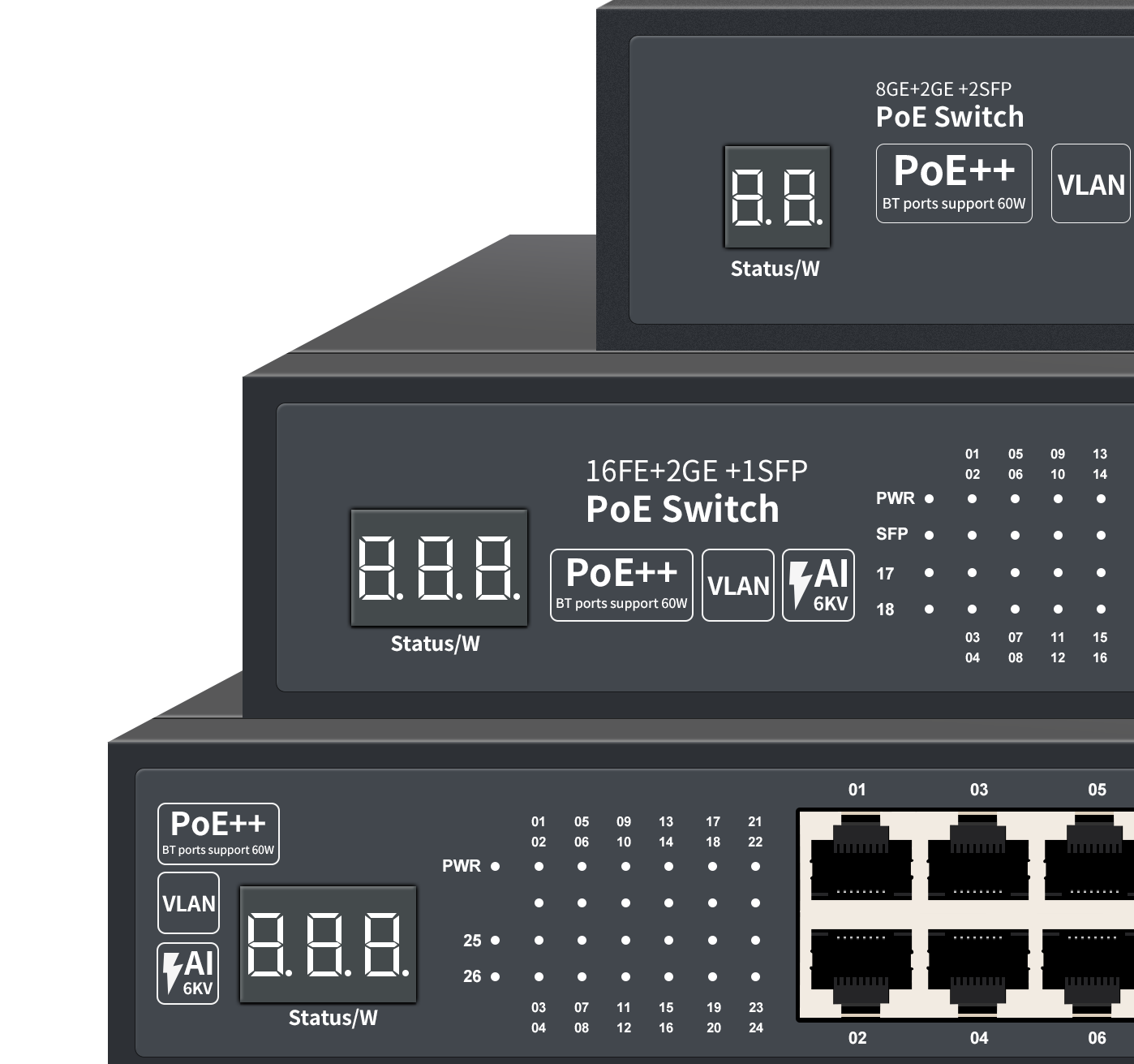
| PoE++ (802.3bt) | 100m (limited by gauge) | 2.5G/5G/10G links possible | Multi-sensor panoramic cameras, speed domes with wipers. | Heat is the enemy. High-power 60W delivery over a bundled 24-port cable snake can overheat the switch’s internal PSU, throttling back power output silently. |
| Single-mode Fiber (SMF) | 10km to 80km+ | Perfect, immune to EMI, low latency. | Inter-building links, farm perimeter networks, electrical substations. | Watch the SFP module compatibility. High-temp SFP modules cost double but don’t die in outdoor enclosures. Cheap SFPs lock up weekly in the heat. |
6. Math in the Mud: Calculating a Real Campus Setup
A system on paper works perfectly. A real build works the moment you account for the physical gate constraints. Here is a walk-through for a mid-size logistics yard. The spec calls for 80 cameras.
- 40 fixed domes (4MP, H.265+): Average draw 3.2 Mbps each. Total: 128 Mbps.
- 30 license plate capture units (2MP, H.264): Constant 8 Mbps each (due to high motion, high fps). Total: 240 Mbps.
- 10 PTZ tracking cameras (2MP, H.264): 6 Mbps average, but 10 Mbps spike during patrol. Total: 60 Mbps (base) to 100 Mbps (burst).
Step 1: Access Isolation.
The LPR cameras spike hard. They sit on a dedicated 24-port switch with a fat backplane. We can’t share this segment with background recording cams. The constant high-bitrate stream fills the switch’s packet buffer, but leaves enough headroom with a switching capacity of 56 Gbps.
Step 2: Layer 3 Routing.
The static domes aggregate on two 24-port PoE+ switches. Each switch pushes roughly 65 Mbps of dome traffic. The uplink is fiber to the core. We avoid copper uplinks here because the distance to the cabinet exceeds 90 meters. Copper would lock the link at 100 Mbps and ruin the buffer. Fiber gives us a full gigabit lane.
Step 3: The Core Calculation.
Total incoming traffic on the core switch: 128 (domes) + 240 (LPR) + 100 (PTZ) = 468 Mbps. That is the “steady state.” The NVR records this on a 10G fiber trunk. The live viewing client, however, pulls a 16-screen multiview, requesting a reduced sub-stream from 16 cameras. That tacks on another 32 Mbps. The core switch’s switching capacity (128 Gbps) easily switches this traffic, but the fan-out to the viewing client must traverse a 1G copper port. That port runs at 80% utilization constantly. No room for error.
7. Wiring Brainworms: Industry Myths That Kill Perimeters
Some misconceptions survive on forums and job site chatter for years. Let us put a stake in a few.
“Plugging a Gigabit switch into a 100M router makes everything faster.”
It does not. Traffic between the cameras and the NVR on the switch stays at wire-speed gigabit. However, any feed hauled through the router bottleneck caps at 100M. If the NVR sits on the router port, every camera stream bottlenecks to 100M. That bandwidth splits among all cameras. The switch sits idle while the router link collapses. Always connect the NVR to the highest bandwidth port on the aggregation switch, not a router LAN port.
“My switch has 16 ports, so I can hook up 16 cameras.”
PoE budget often says no. A 16-port switch with a 65W budget handles three high-power PTZs at most. The physical port count is not the metric. The math is: Total PoE budget / Camera peak draw = Max cameras. On PTZ installs with heaters, this often cuts your usable port count in half.
“Cat6 cable automagically gives me gigabit over 200 meters.”
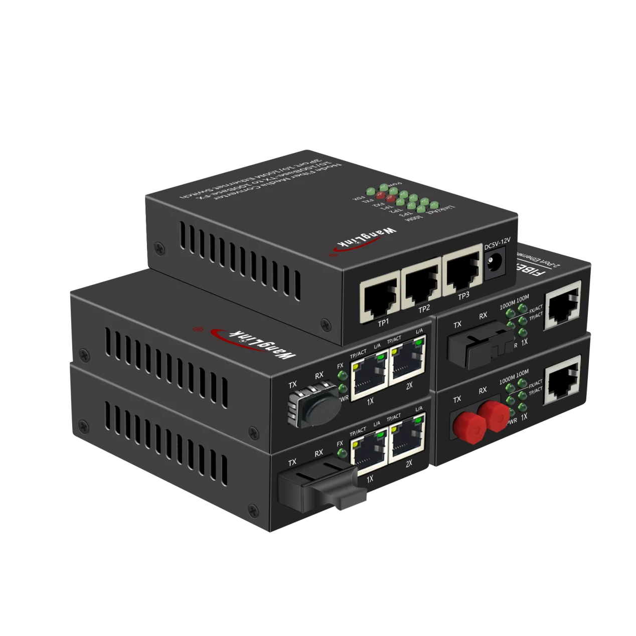
The Ethernet standard cuts the signal at 100 meters (328 feet). The cable does not know it is Cat6. Over 100m, signal attenuation rises. The link might negotiate gigabit in the afternoon cold but fail when the cable warms up in the morning sun. Copper is copper. For runs over 80 meters outdoors, we skip the headache and install a media converter with fiber. It is cheaper than rolling a truck back two months later.