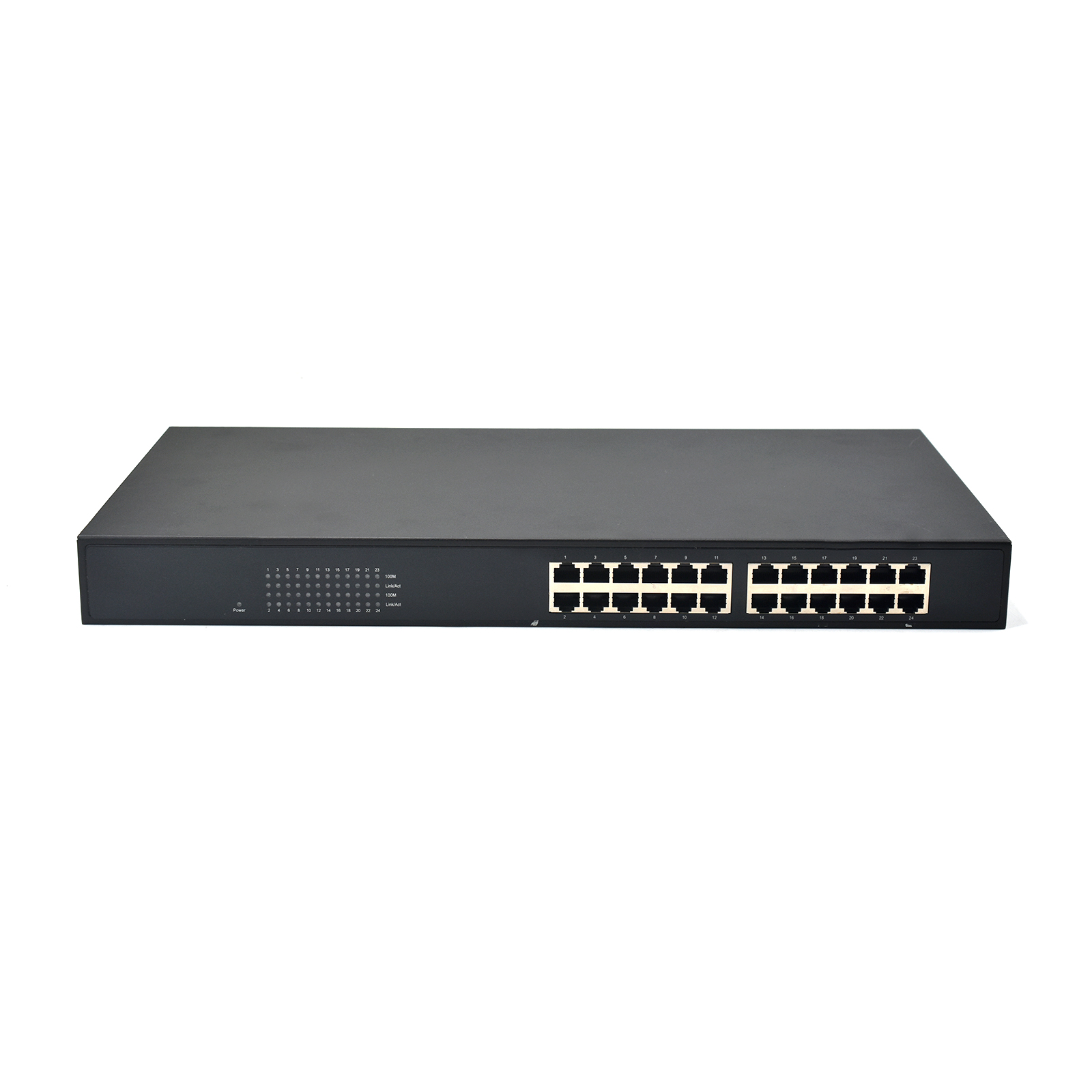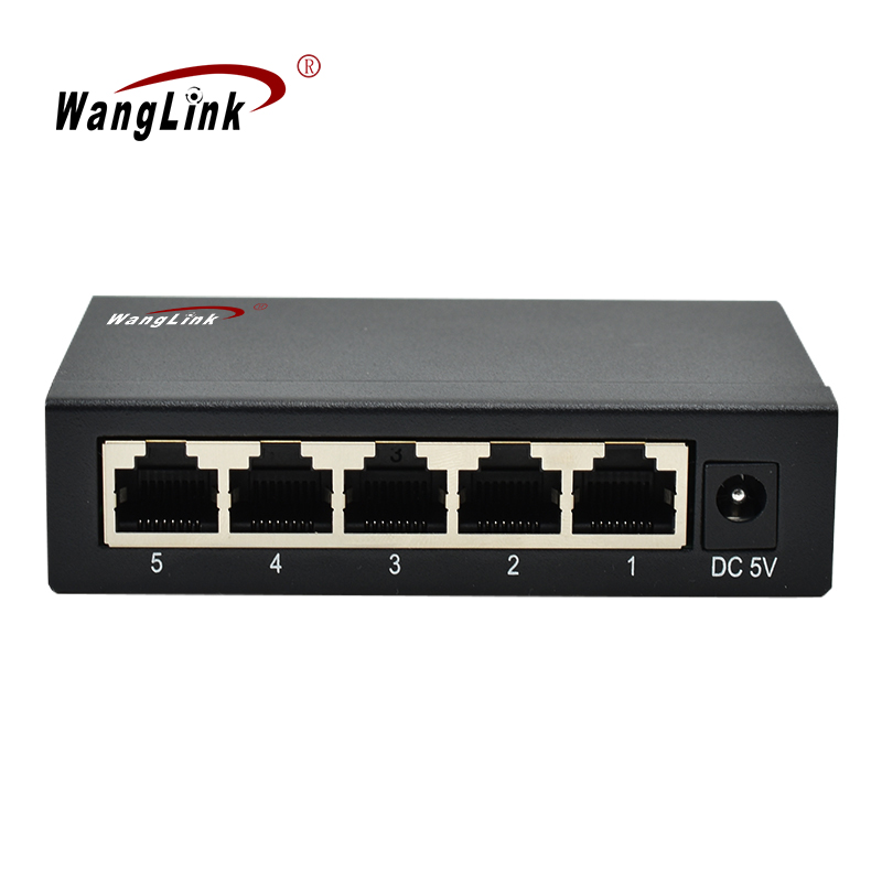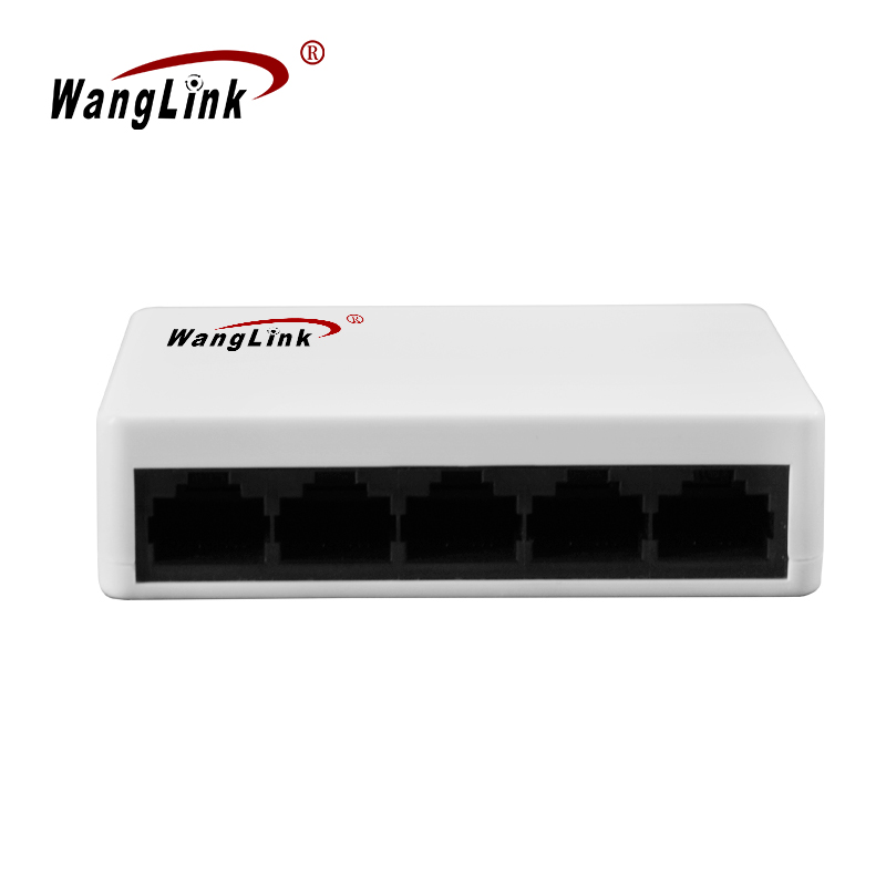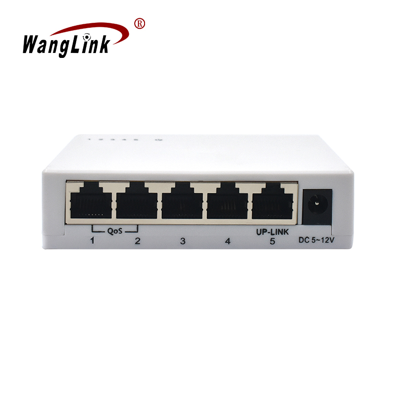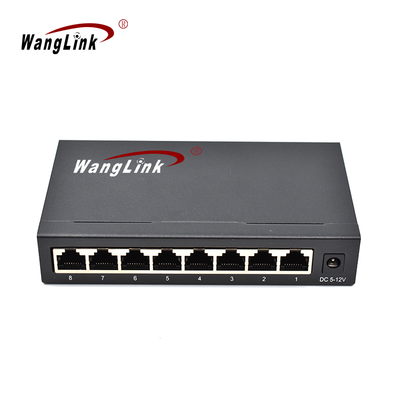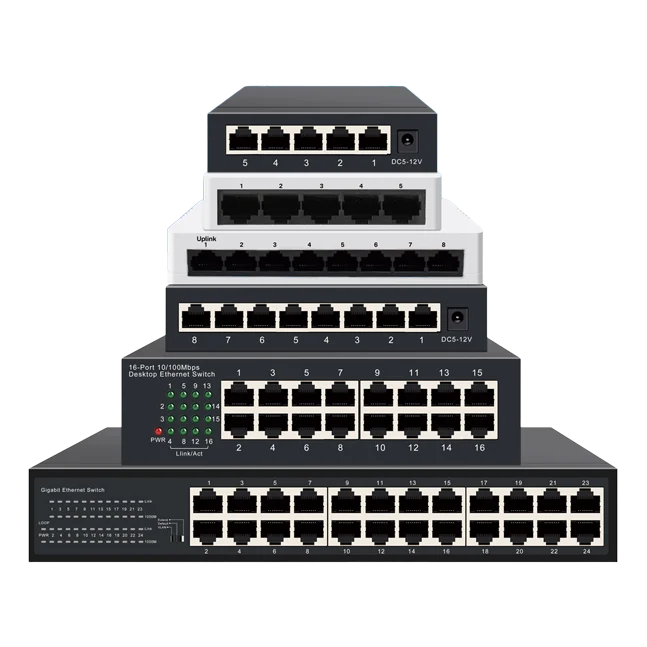
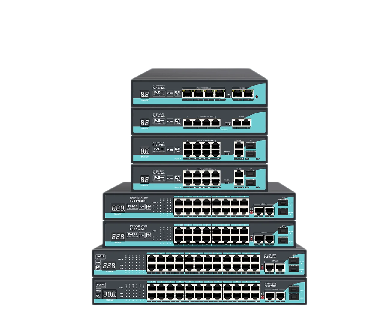
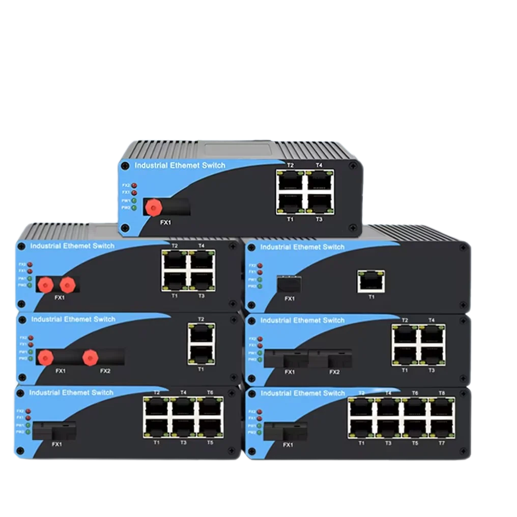
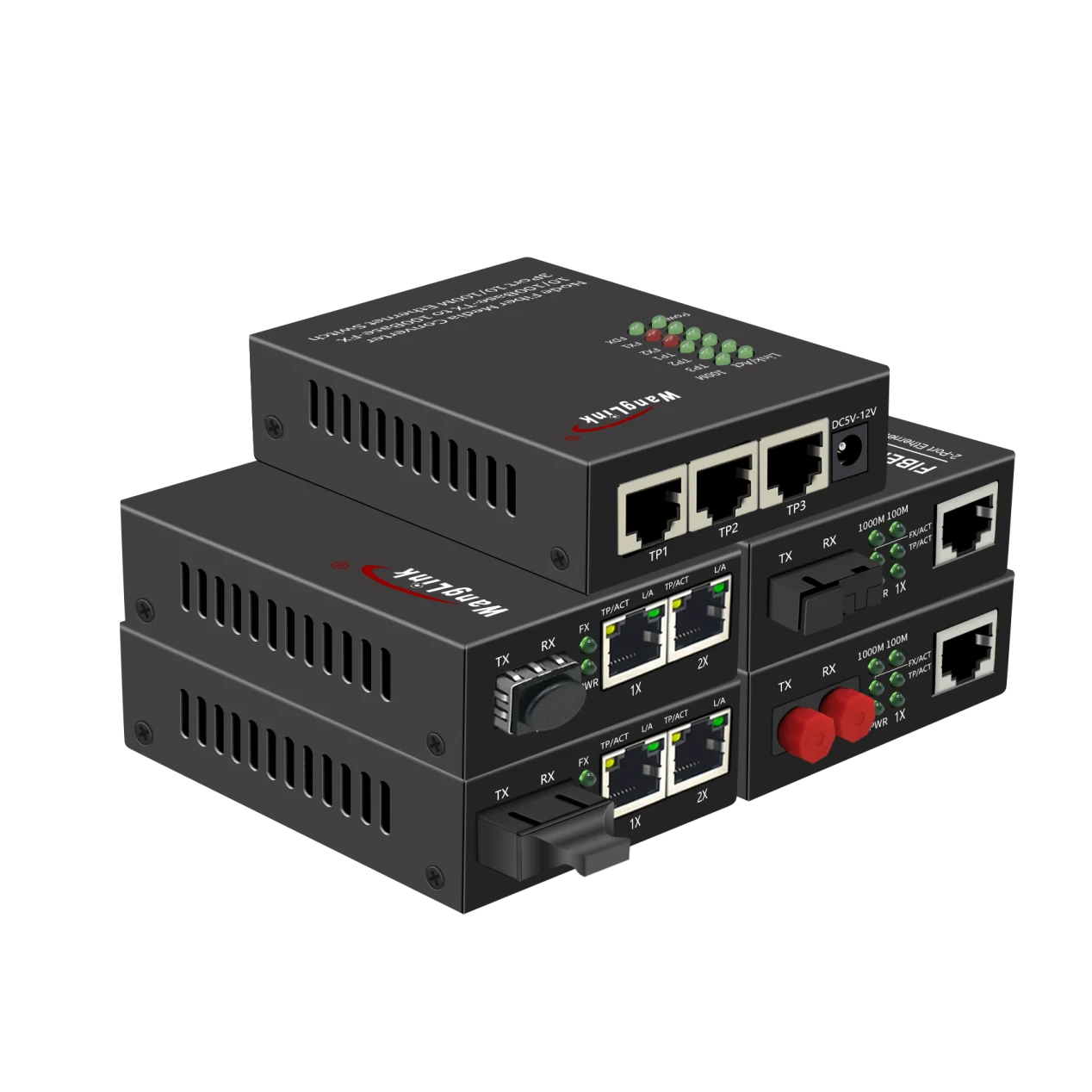
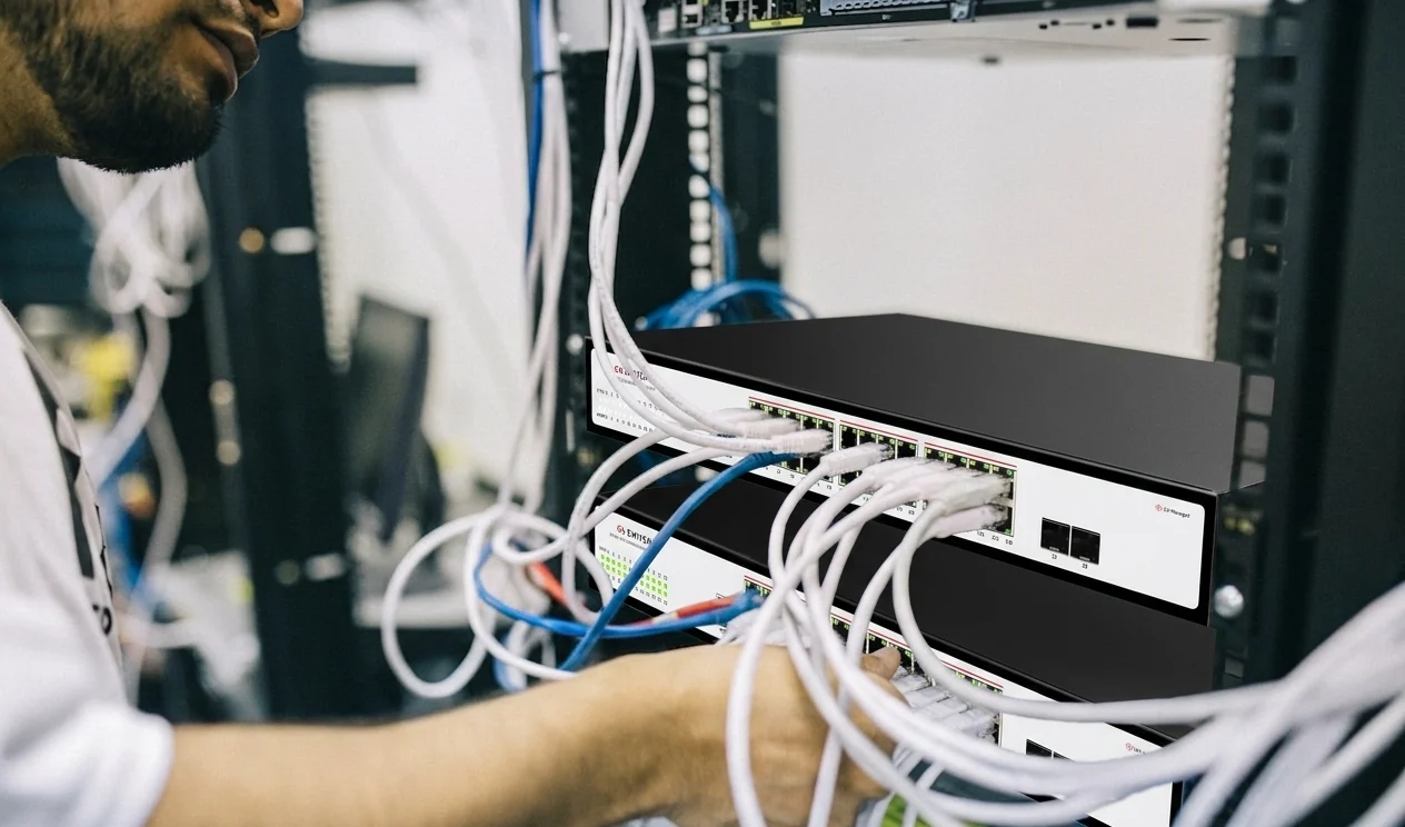
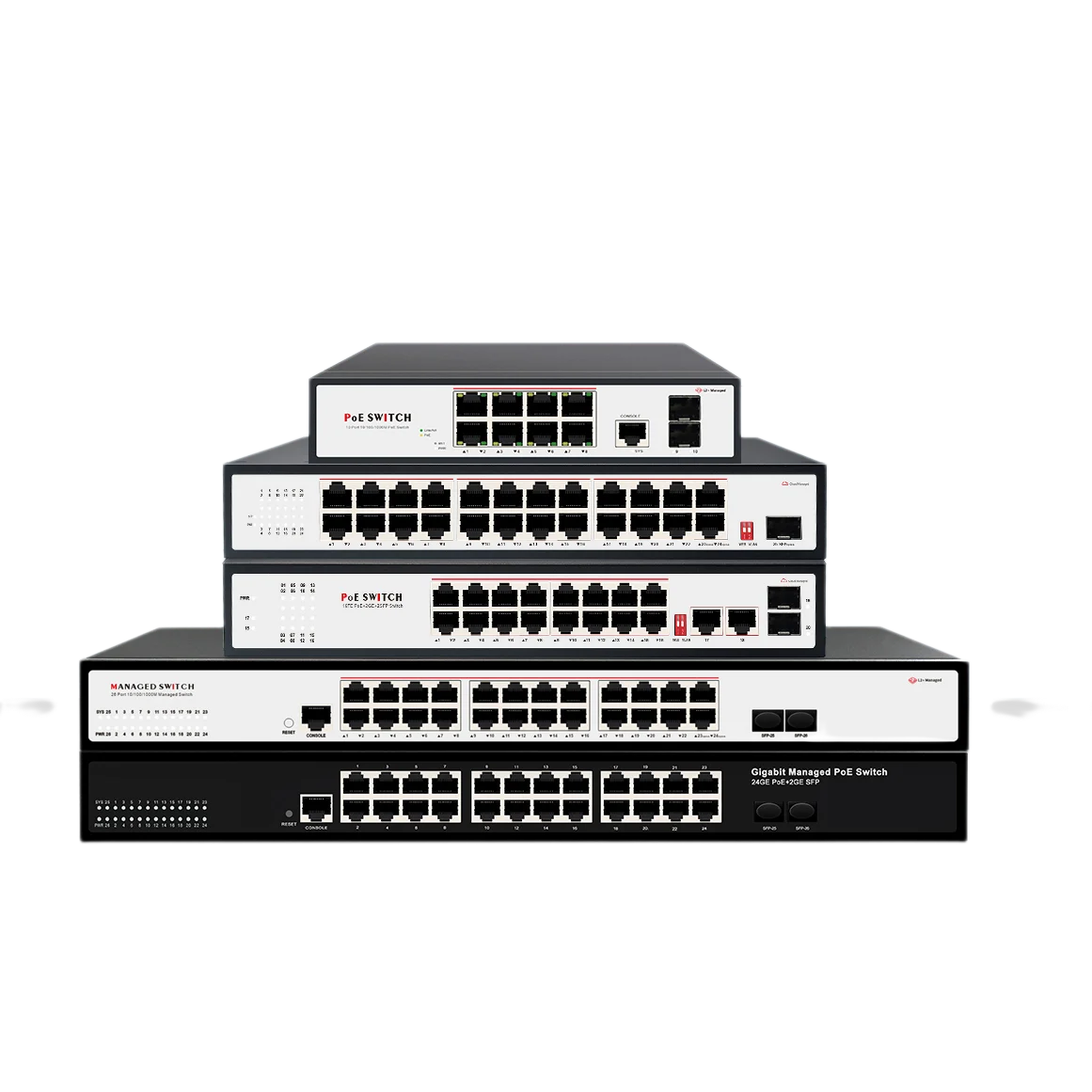
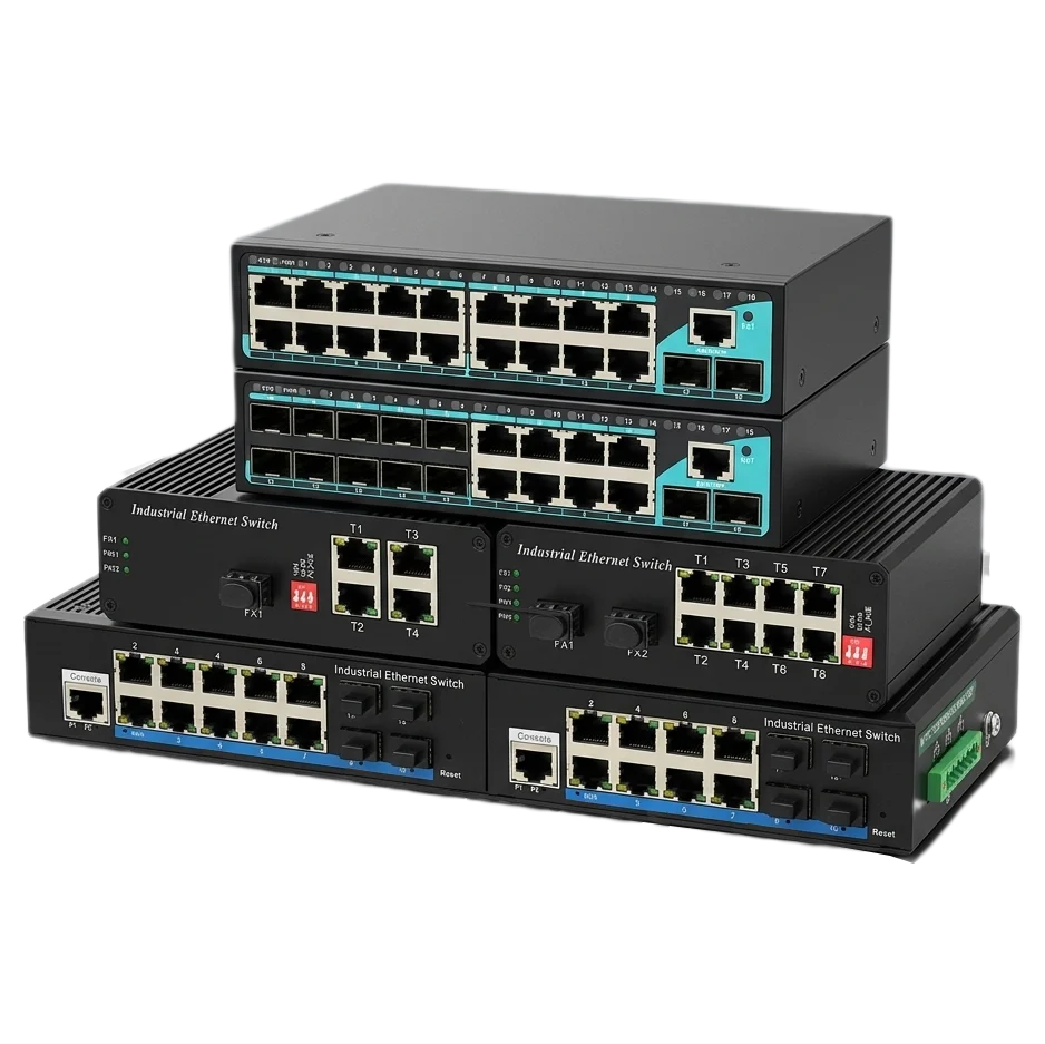

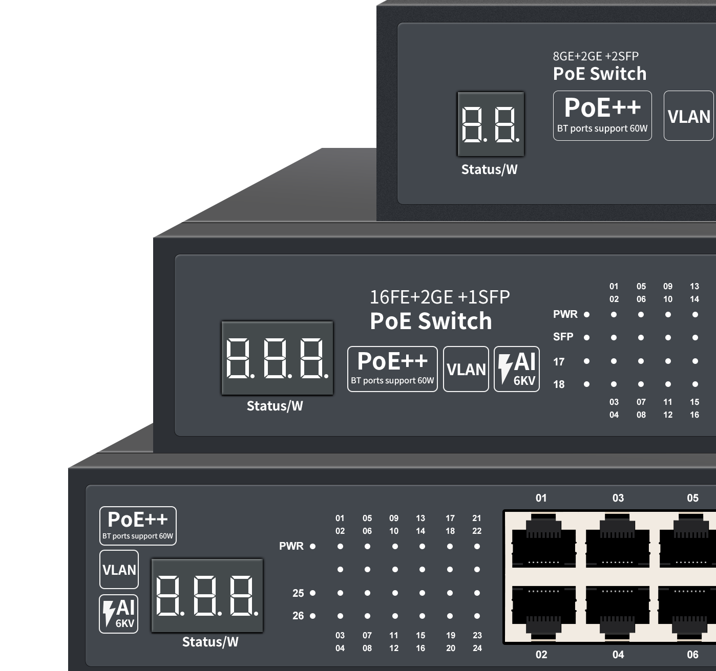

A network switch connects devices within the same Local Area Network (LAN) and forwards Ethernet frames to the correct destination port. It identifies devices by their Media Access Control (MAC) addresses, stores this information in a MAC address table, and uses the table to make forwarding decisions.
Unlike a traditional hub, a switch does not normally send every frame to every port. This reduces unnecessary traffic and improves network efficiency. Managed switches can also provide VLAN segmentation, traffic monitoring, Quality of Service (QoS), redundancy, and security controls.
Network switches are widely used in offices, factories, surveillance systems, transportation infrastructure, campuses, and data centers. Wanglink provides network communication solutions for a range of Ethernet networking applications.
1. Project Background & Technical Challenges
Modern business and industrial networks connect many types of devices, including:
- Computers and servers
- IP phones
- Wireless access points
- IP cameras
- Industrial controllers
- Sensors and automation equipment
- Network gateways and firewalls
- Building management systems
These devices must exchange data reliably while sharing the same physical network infrastructure. A network switch manages this local communication and determines where each Ethernet frame should go.
Without switching, network traffic can become inefficient. If every device receives every frame, connected devices must process traffic that is not intended for them. This can increase congestion, reduce available bandwidth, and make troubleshooting more difficult.
Industrial and enterprise networks may also face additional requirements:
- Separate office, production, security, and guest traffic
- Deliver power to cameras, phones, or access points
- Maintain connectivity if a link or device fails
- Support long-distance fiber or copper connections
- Operate continuously in electrically noisy environments
- Prioritize real-time voice, video, or control traffic
- Provide visibility into network status and faults
The correct switch architecture depends on the network size, traffic type, security requirements, physical environment, and expected availability.
2. How Does a Network Switch Work?
2.1 A Switch Connects Devices at the Ethernet Layer
A conventional Ethernet switch primarily operates at Layer 2 of the OSI model, the Data Link Layer. It uses MAC addresses to identify network interfaces and make forwarding decisions.
Every Ethernet-enabled device has a MAC address, normally represented as a 48-bit hexadecimal value, such as:
00:1A:2B:3C:4D:5EWhen a device sends an Ethernet frame, the frame typically contains:
- Source MAC address
- Destination MAC address
- Payload data
- Frame integrity information
The switch reads the frame header and determines which port should receive the frame.
2.2 The Switch Learns MAC Addresses
A switch builds a forwarding database, also called a MAC address table, by examining the source MAC address of incoming frames.
For example:
Port 1: 00:11:22:33:44:55
Port 2: 00:11:22:33:44:66
Port 3: 00:11:22:33:44:77
If the switch receives a frame from the device connected to Port 1, it records that the source MAC address is reachable through Port 1.
This learning process is automatic. The switch continues updating the table as devices send traffic or move to different ports.
2.3 The Switch Forwards Frames to the Correct Port
When a frame arrives, the switch checks the destination MAC address against its MAC address table.
The basic forwarding process is:
- The switch receives an Ethernet frame.
- It reads the source MAC address.
- It updates or refreshes the source MAC-to-port entry.
- It reads the destination MAC address.
- It searches the forwarding database.
- It forwards the frame to the associated port if the destination is known.
- It floods the frame within the relevant VLAN if the destination is unknown or broadcast.
- It discards the frame if filtering rules or VLAN configuration prevent forwarding.
A simplified network flow looks like this:
Device A
   |
   | Ethernet frame
   v
[Network Switch]
   |
   | MAC table lookup
   v
Device B
If Device B is known to be connected to Port 4, the switch forwards the frame only through Port 4 rather than sending it to every connected device.
2.4 What Happens When the Destination Is Unknown?
If the switch has not yet learned the destination MAC address, it usually floods the frame to all other ports within the same VLAN, except the port where the frame arrived.
When the destination device replies, the switch learns its MAC address and can normally forward later frames more efficiently.
Broadcast frames, such as Address Resolution Protocol (ARP) requests, are also distributed within the applicable broadcast domain. VLANs can be used to control the size and scope of that domain.
2.5 Full-Duplex Communication and Collision Reduction
Modern Ethernet switches typically support full-duplex communication. This allows a device to transmit and receive at the same time over a dedicated switch link.
Because each device generally has its own point-to-point connection to the switch, traditional Ethernet collisions are eliminated on full-duplex links. This provides more predictable performance than older shared-media networks based on hubs.
Actual throughput depends on several factors, including:
- Port speed
- Uplink capacity
- Switching capacity
- Packet size
- Traffic direction
- Oversubscription
- Buffer capacity
- Network design and configuration
A switch with many high-speed access ports may require higher-capacity uplinks to prevent congestion between access and core layers.
3. The Network Architecture & Solution Design
3.1 Basic Office Network Topology
A typical small or medium-sized network may use the following structure:
Internet
   |
[Firewall / Router]
   |
[Core or Aggregation Switch]
   |--------- Server
   |--------- Access Switch
   |--------- Wireless Access Point
   |--------- IP Phone
   |--------- Network Printer
In this design:
- The router or firewall connects the LAN to external networks.
- The switch connects local devices to each other.
- The access switch provides additional ports for end devices.
- The uplink connects access-layer traffic to the core or aggregation layer.
A switch can connect devices within the same LAN, but it does not automatically provide Internet access. A router, Layer 3 switch, or firewall is normally required for communication between different IP networks or between the LAN and the Internet.
3.2 VLAN Segmentation
A managed switch can divide one physical switching infrastructure into multiple logical networks using Virtual Local Area Networks (VLANs).
For example:
VLAN 10: Office computers
VLAN 20: Voice services
VLAN 30: IP surveillance
VLAN 40: Industrial control
VLAN 50: Guest access
VLAN segmentation can help organizations:
- Limit broadcast traffic
- Separate sensitive systems
- Apply different security policies
- Prioritize critical traffic
- Simplify network administration
- Reduce the impact of a problem in one network segment
A switch port may be configured as an access port for a single VLAN or as a trunk port that carries multiple VLANs between switches, routers, firewalls, or servers.
3.3 Managed and Unmanaged Switches
Unmanaged Switches
An unmanaged switch operates with a basic plug-and-play configuration. It generally learns MAC addresses and forwards frames without requiring manual setup.
Unmanaged switches may be appropriate for:
- Small office networks
- Simple machine connections
- Temporary installations
- Non-critical device expansion
- Basic point-to-point Ethernet connectivity
They usually provide limited visibility and configuration control.
Managed Switches
A managed switch provides configuration and monitoring functions through a web interface, command-line interface, network management platform, or other management method.
Depending on the model, managed features may include:
- VLAN configuration
- Link aggregation
- Port mirroring
- QoS
- Access control lists
- Spanning Tree Protocol
- Loop protection
- IGMP Snooping
- SNMP monitoring
- Port statistics
- Event logs and alarms
- Firmware management
Managed switching is generally more suitable for networks that require segmentation, diagnostics, redundancy, or policy enforcement.
3.4 PoE Network Switches
A Power over Ethernet (PoE) switch can transmit data and electrical power through the same Ethernet cable to compatible devices.
Common PoE endpoints include:
- IP cameras
- Wireless access points
- VoIP phones
- Intercom systems
- Access control devices
- IoT gateways
PoE deployment should account for:
- The PoE standard supported by the switch
- The power requirement of each endpoint
- Total PoE power budget
- Cable length and quality
- Temperature and installation conditions
- Backup power requirements
The total power budget is especially important. A switch may have PoE capability on every port, but it may not be able to provide the maximum power level to every port simultaneously.
3.5 Redundancy and Loop Prevention
Redundant links can improve network availability, but physically connecting switches in a loop can create broadcast storms and unstable forwarding behavior.
Spanning Tree Protocol technologies are used to prevent harmful Layer 2 loops. Depending on network requirements, deployments may use:
- STP
- RSTP
- MSTP
- Vendor-specific ring protection mechanisms
- Link aggregation for resilient connections
A resilient topology may look like this:
             [Core Switch A]
              /           \
             /             \
[Access Switch 1]       [Access Switch 2]
             \             /
              \           /
             [Core Switch B]
The network control protocol determines which links forward traffic and which links remain available as backups. The exact recovery time depends on the protocol, topology, configuration, device performance, and failure type.
4. Why Network Switches Are Selected for Different Applications
The right switch is determined by the application rather than by port count alone.
4.1 Key Selection Criteria
| Requirement | Technical Consideration |
|---|---|
| Number of connected devices | Access port count and expansion capacity |
| Traffic volume | Port speed, switching capacity, and uplink bandwidth |
| Network segmentation | VLAN, trunking, and Layer 3 capabilities |
| Video or voice traffic | QoS, multicast handling, and buffer performance |
| IP cameras or access points | PoE standard and total power budget |
| High availability | RSTP, MSTP, ring protection, or link aggregation |
| Remote monitoring | SNMP, event logs, alarms, and diagnostics |
| Industrial deployment | Temperature range, EMC performance, and mounting options |
| Long-distance connections | Fiber interfaces and transceiver compatibility |
| Cybersecurity | Access control, port security, authentication, and firmware support |
4.2 Switching Capacity and Forwarding Performance
Two commonly referenced switch specifications are switching capacity and forwarding rate.
Switching capacity describes the aggregate data-handling capability of the switching fabric, normally expressed in Gbps.
Forwarding rate describes how many packets the switch can process per second, normally expressed in Mpps.
A theoretical forwarding-rate calculation for minimum-sized Ethernet packets can be approximated as:
Forwarding rate = Port rate / Packet transmission timeIn practical network design, engineers should also consider:
- Packet size distribution
- Full-duplex traffic
- Ingress and egress direction
- Uplink oversubscription
- Internal architecture
- Packet buffering
- Feature impact
- Actual traffic patterns
A switch should be evaluated against the expected workload rather than one isolated specification.
4.3 Environmental Requirements
For industrial or outdoor applications, the switch may need to withstand conditions that do not exist in a controlled office environment.
Important factors may include:
- Operating temperature
- Humidity
- Vibration and shock
- Electromagnetic interference
- Surge and electrostatic discharge
- Dust and enclosure protection
- DC or redundant power input
- DIN-rail or wall mounting
- Fiber isolation for long-distance links
Environmental specifications should be verified against the actual installation location. A switch rated for an extended temperature range may still require appropriate enclosure design, power protection, grounding, and thermal management.
5. Measurable Results & Project Impact
When correctly selected and configured, a network switch can improve a network in several measurable ways:
- More efficient forwarding: Known unicast traffic is sent toward the intended destination port.
- Reduced unnecessary traffic: VLANs and proper topology design limit broadcast domains.
- Higher available bandwidth: Full-duplex links allow simultaneous transmission and reception.
- Simpler expansion: Additional endpoints can be connected through access ports or downstream switches.
- Improved fault isolation: VLANs, port statistics, logs, and alarms help identify problem areas.
- Better service continuity: Redundant links and loop-prevention protocols support resilient designs.
- Lower installation complexity: PoE can combine data and power delivery over one cable.
- Greater operational visibility: Managed switches provide information about link status, errors, traffic, and connected devices.
Actual results depend on the switch specifications, topology, traffic profile, cable infrastructure, configuration quality, and maintenance procedures. A reliable network design should validate performance with real traffic and failure testing rather than relying only on product datasheets.
6. Recommended Network Switch Features
When evaluating a switch for an enterprise or industrial Ethernet application, consider the following feature groups.
Core Switching Functions
- 10/100 Mbps, Gigabit, or higher-speed Ethernet ports
- Full-duplex operation
- MAC address learning
- Auto-negotiation and auto MDI/MDI-X
- Store-and-forward or cut-through architecture
- Adequate switching capacity and forwarding rate
Network Management
- Web-based management
- Command-line management
- VLAN and 802.1Q trunking
- SNMP monitoring
- Port mirroring
- Event logging
- Firmware upgrade capability
Availability and Traffic Control
- RSTP, MSTP, or other loop-prevention features
- Link aggregation
- QoS queues and traffic prioritization
- IGMP Snooping for multicast applications
- Broadcast and multicast storm control
- Link fault alarms
Industrial and Deployment Features
- Extended operating temperature options
- DIN-rail or wall mounting
- Redundant power inputs
- Fiber uplink options
- Industrial EMC and surge protection
- Compact installation dimensions
- Local or remote status indicators
For a specific deployment, the product datasheet should be checked for exact port combinations, supported protocols, PoE budget, environmental ratings, and management features. Explore Wanglink’s network communication solutions for application-specific Ethernet connectivity options.
7. Network Switch vs. Router: What Is the Difference?
A network switch and a router perform different functions.
| Device | Main Function | Typical Address Used |
|---|---|---|
| Network switch | Connects devices within a LAN | MAC address |
| Router | Connects different IP networks | IP address |
| Firewall | Controls and inspects traffic according to security policies | IP, port, application, and identity rules |
| Wireless access point | Provides Wi-Fi connectivity | Bridges wireless and wired networks |
A basic Layer 2 switch forwards frames within a VLAN. A router or Layer 3 switch is needed to route traffic between different IP subnets.
Some enterprise switches support Layer 3 routing functions, which can reduce the need for a separate routing device in certain network architectures. The appropriate design depends on security boundaries, routing requirements, scalability, and operational policy.
8. Frequently Asked Questions
How does a network switch know where to send data?
A switch learns the source MAC address of incoming frames and associates each address with the port where it was received. When a frame arrives, the switch checks the destination MAC address in its MAC address table and forwards the frame through the corresponding port.
Does a network switch provide Internet access?
Not by itself. A switch connects devices within a local network. Internet access normally requires a router, firewall, or Layer 3 device connected to an Internet service.
What happens if a switch does not know the destination MAC address?
The switch normally floods the frame within the same VLAN, excluding the ingress port. Once it learns the destination device’s MAC address, subsequent frames can be forwarded directly.
Can a network switch improve Internet speed?
A switch cannot increase the bandwidth purchased from an Internet service provider. However, a correctly selected switch can prevent local network bottlenecks and provide sufficient capacity for internal traffic.
What is the difference between a managed and unmanaged switch?
An unmanaged switch provides basic automatic Ethernet forwarding with little configuration. A managed switch supports features such as VLANs, monitoring, QoS, redundancy, security controls, and diagnostic tools.
How does a PoE switch work?
A PoE switch sends Ethernet data and electrical power over compatible twisted-pair cable to a powered device. The switch and endpoint negotiate power requirements according to the supported PoE standard.
Can switches be connected in a loop?
Switches can be connected with redundant links, but an uncontrolled Layer 2 loop can cause broadcast storms and unstable network behavior. Loop-prevention or ring-redundancy protocols must be configured for redundant topologies.
Conclusion
A network switch works by receiving Ethernet frames, learning MAC addresses, checking its forwarding database, and sending traffic toward the appropriate port. This basic process enables efficient communication between devices on the same LAN.
More advanced switches extend this function with VLAN segmentation, PoE, QoS, multicast control, monitoring, security, and redundancy. For office, industrial, surveillance, transportation, and campus networks, switch selection should be based on the complete application: traffic load, port requirements, environmental conditions, availability targets, power delivery, and management needs.
Ready to Design a More Reliable Ethernet Network?
Discuss your port, bandwidth, PoE, VLAN, fiber, and redundancy requirements with the Wanglink network solutions team to identify a switch architecture suitable for your application.