

• What Is a PoE Media Converter? Working Principle, Types & Selection Guide

    What Is a PoE Media Converter? Working Principle, Types & Selection Guide

    Quick answer: A PoE media converter is a two-in-one network device that converts optical fiber signals to copper Ethernet on its RJ45 side and injects Power over Ethernet (PoE) through that same copper port. One box therefore does two jobs: it extends a link beyond the 100 m (328 ft) twisted-pair limit, and it powers a remote device such as an IP camera, wireless access point, or door controller without a local power outlet.

    If you have ever tried to mount a camera on a light pole 200 meters from the nearest switch, you have already met the two problems this device solves: copper Ethernet stops at 100 meters, and fiber — while it carries data for kilometers — carries no electricity at all. A PoE media converter bridges exactly that gap, which is why it has become a staple in perimeter surveillance, campus Wi-Fi, and industrial networking.

    How Does a PoE Media Converter Work?
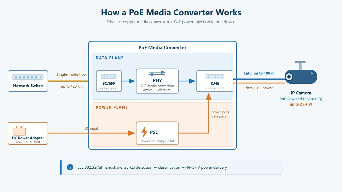
    How a PoE media converter works: single-mode fiber (up to 120 km) enters the SC/SFP optical port, the PHY converts optical signals to electrical, and a Cat6 cable (up to 100 m) carries both data and PoE power to a PD such as an IP camera (up to 25.4 W), with a 48-52 V DC adapter feeding the internal PSE circuit.
    How a PoE media converter works: fiber-to-copper conversion on the data plane, DC-fed PoE injection on the power plane.

    To understand the box, think of it as two independent planes running in one chassis: a data plane and a power plane.

    Data plane: fiber to copper conversion

    On the fiber side, the converter terminates an SC connector or an SFP transceiver module. The optical signal is converted by the PHY layer into an electrical Ethernet signal and forwarded to the RJ45 copper port. The conversion happens at Layer 1 — the device is transparent to MAC addresses, VLAN tags, and IP packets. There is no IP address to configure and no software to install: in the field, we typically power the unit, plug in fiber and copper, and see the link LED turn green in under a minute. Jumbo frames up to 9 KB pass through on most models, which matters if your cameras send large multicast bursts.

    Power plane: where the PoE actually comes from

    This is the part that trips up even experienced installers: PoE does not travel over fiber. Glass carries light, not electricity. So the converter is powered locally — usually from a 48–52 V DC adapter or a rack power supply — and its internal PSE (power sourcing equipment) circuit injects power onto the copper pairs going out to the end device.

    The injection follows the standard IEEE handshake sequence. When the remote PD (powered device) connects, the PSE first measures the 25 kΩ signature resistance to confirm it is PoE-safe, then classifies it (Class 0–4 under 802.3af/at) to decide how much power to allocate, and only then ramps the port up to 44–57 V. If the handshake fails — for example if someone plugs in a non-PoE laptop — the port stays a plain data port and delivers no voltage. This is why you cannot “fry” a regular device by plugging it into a standards-compliant PoE port.

    The power classes you will encounter in practice:

    IEEE standard PSE output per port Power guaranteed at PD Typical loads
    802.3af (Type 1) 15.4 W 12.95 W Fixed dome cameras, IP phones
    802.3at (Type 2) 30 W 25.5 W PTZ cameras, Wi-Fi 6 APs, intercoms
    802.3bt (Type 3/4) 60 / 90 W 51 / 71 W High-power APs, digital signage (model-dependent)

    Most current PoE media converters on the market — including the units we build at Wanglink — cover 802.3af/at, delivering up to 25.4 W per port at the far end. That covers the overwhelming majority of cameras and access points deployed today.

    PoE vs. Non-PoE Media Converters: What Actually Changes

    A standard (non-PoE) media converter does the same fiber-to-copper conversion but leaves the remote device to find its own power. That single difference cascades through the whole installation:

    Aspect PoE media converter Standard media converter
    Powers the end device Yes — via the RJ45 port No — device needs its own PSU or a separate injector
    Local outlet at the device Not required Required (or a second injector box)
    Boxes hanging at the far end 1 2–3
    Remote power cycling Easy — cycle the converter Hard — outlet is at the device
    Outdoor/weatherproof installs Simple: one IP-rated box Complex: more enclosures, more failure points
    Best for IP cameras, APs, door controllers Routers, servers, already-powered equipment

    The practical takeaway from dozens of installations: whenever the remote device is PoE-capable, a PoE-capable converter is almost always cheaper and more reliable than a plain converter plus a separate injector, because you eliminate one enclosure, one power run, and one point of failure per site.

    Types of PoE Media Converters

    “PoE media converter” is a category, not a single product. The variations you will see in datasheets break down along three axes.

    1. By fiber interface: fixed SC vs. SFP slot

    Fixed-SC models have the optic soldered in — single-mode or multimode, chosen at purchase. They are cheaper and ideal for closed, single-vendor deployments. SFP-slot models take pluggable transceivers, so you can stock one converter SKU and swap between 20 km, 40 km, or 120 km optics, or between single-mode and multimode, as each site requires. For system integrators maintaining spare parts across many sites, SFP flexibility usually pays for itself the first time a customer changes the fiber plan.

    2. By speed: 100M, 1G, 2.5G

    Fast Ethernet converters (155 Mbps optical) still dominate budget camera backhaul. Gigabit models (10/100/1000 RJ45, 1.25 G optical) are the current mainstream and the safe default. A newer class of 2.5G media converter with an SFP slot answers Wi-Fi 6/6E uplinks and multi-camera aggregation, where a single 1G link starts to pinch. As a rule of thumb from our deployment experience: size the fiber uplink at least 40% above your measured peak traffic — bandwidth is cheap at design time and expensive to retrofit.

    3. By PoE port count

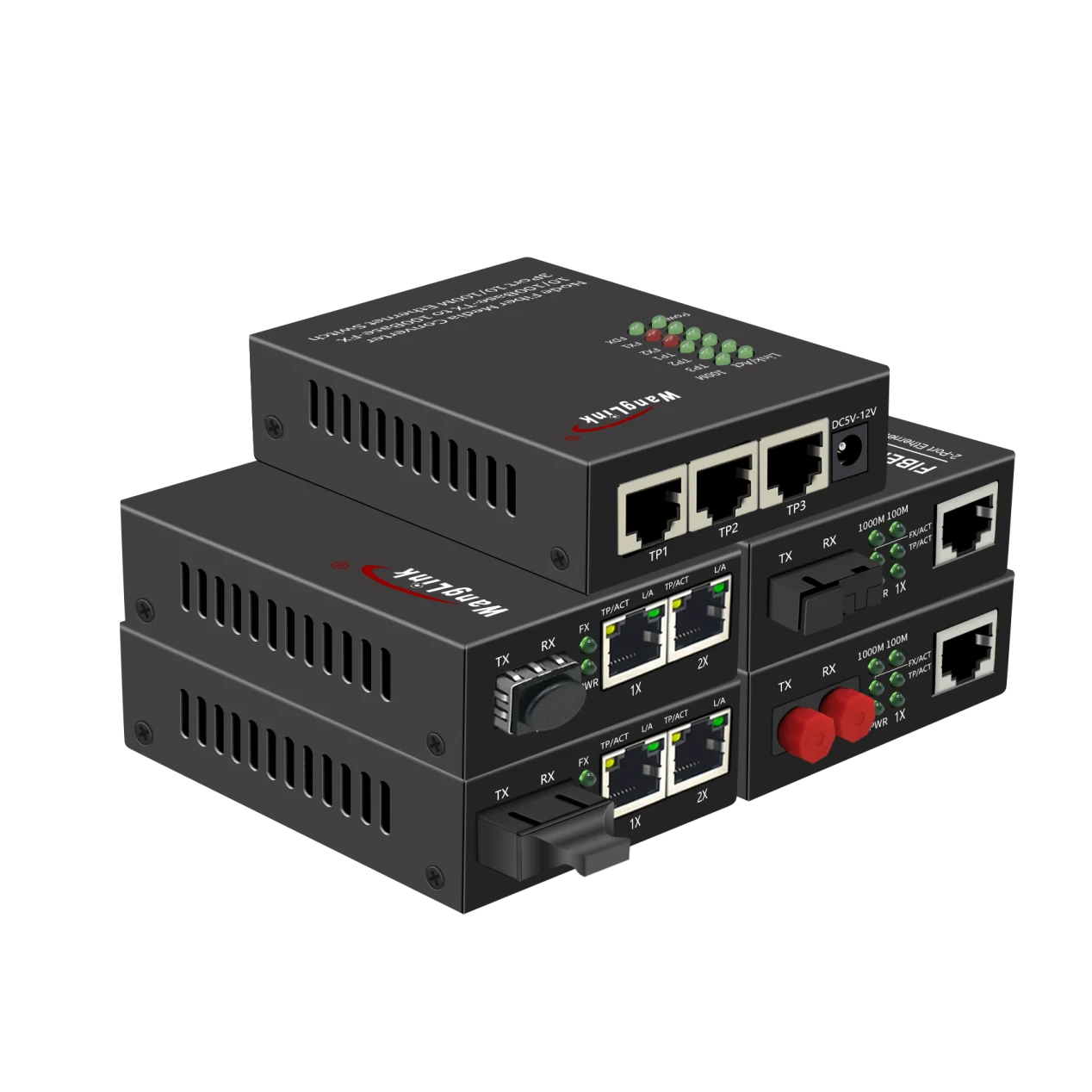
    A 1-port gigabit PoE media converter is the classic “camera on a pole” unit: one fiber in, one powered RJ45 out. When two to eight devices sit within 100 m of each other — a cluster of cameras at a gate, an AP plus two cameras on a building corner — a multi-port unit such as a 4-port PoE media converter or an 8-port gigabit PoE media converter with 25.4 W per port replaces several single-port boxes and a small switch. These multi-port units are effectively “fiber-to-PoE switches” — the 2.5G media converter with an SFP slot covers the same job where the uplink must run above gigabit.

    Terminology note: you will see “fiber to Ethernet media converter with PoE”, “PoE fiber converter”, and “PoE-to-fiber switch” used interchangeably in the market. They describe the same family of devices; check the port table, not the label.

    Selection Guide: Matching the Converter to the Site

    The five decisions below cover 95% of real deployments. Work through them in order:

    Your requirement Recommended choice
    Distance under 2 km, existing multimode plant Multimode SC converter (100Base-FX / 1000Base-SX)
    Distance 2–120 km, new single-mode fiber Single-mode SC or SFP converter (20/40/60/120 km optics)
    Mixed sites, spare-parts flexibility, future optics changes SFP-slot model over fixed-SC
    One PoE device at the far end 1-port PoE media converter
    3–8 devices clustered within 100 m 4- or 8-port PoE media converter (check per-port W and total budget)
    Uplink demand approaching 1 Gbps 2.5G SFP model
    End device draws ≤ 12 W 802.3af support is sufficient
    PTZ, Wi-Fi 6 AP, or device drawing 12–25 W 802.3at support (25.4 W class) required
    Outdoor pole, roadside cabinet, elevator shaft Metal housing + port surge protection (up to 4 kV on some models) — confirm on the datasheet

    Two details that datasheets underplay: surge protection and mounting. A converter on a pole shares a ground path with lightning-prone steelwork; models with port-level surge protection (up to 4 kV) measurably reduce field failures. And check for DIN-rail or wall-mount ears if the unit lives in a cabinet — desktop-only casings waste rack space.

    Also verify how the unit handles the reverse situation: what happens when the PD draws nothing. Quality converters detect the disconnect and cut power within milliseconds, which both saves energy and lets you power-cycle a hung camera remotely by toggling the converter.

    Typical Application Scenarios

    Scenario 1: Perimeter camera beyond the 100 m copper limit

    A warehouse perimeter needs a camera at a gate 220 m from the IDF rack. Copper is out of spec at that length; pulling a new power circuit to the gate costs far more than the camera. The standard fix: run single-mode fiber in the existing conduit, mount a PoE fiber converter in a small IP65 box at the pole, and deliver both data and power over the last meters of Cat6. One fiber strand, one DC adapter at the pole, camera online.

    Scenario 2: Building-to-building campus links

    Two office blocks 400 m apart, multimode fiber already in the duct. At the far building, a 4-port PoE media converter fans out to two Wi-Fi access points, an IP intercom, and a door controller. No local PoE switch, no electrician — the converter is the powered infrastructure for the whole remote floor.

    Scenario 3: Rural checkpoint or highway surveillance

    Monitoring points 20–120 km apart along a road or pipeline use single-mode optics, often single-fiber bidirectional (WDM) modules that send and receive on one strand to halve fiber usage. At each checkpoint, an 8-port converter with 25.4 W per port aggregates the local camera cluster onto the long-haul link. This is where the distinction between converter and switch disappears: functionally, you are deploying a compact fiber-fed PoE switch.

    For a deeper comparison of the neighboring PoE device categories — standard PoE, reverse PoE, and non-standard forced power — see our related Knowledge Base article.

    PoE Power Budget: A Worked Example

    Selecting a converter without doing this arithmetic is the most common cause of “mystery” camera reboots at night (when IR illuminators switch on and power draw spikes). Here is the calculation we run on every multi-camera site.

    Site: a gate cluster with 3 fixed 4 MP domes and 1 PTZ speed dome, fed by a 4-port gigabit PoE media converter rated 25.4 W per port.

    Step 1 — list maximum (not typical) power per device (from camera datasheets, IR on):

    Device Qty Max draw Subtotal
    4 MP fixed dome (IR on) 3 6.5 W 19.5 W
    PTZ speed dome (heater off) 1 18 W 18 W
    Total 37.5 W

    Step 2 — add 20% headroom for cable loss and aging: 37.5 × 1.2 = 45 W required from the converter’s total PoE budget.

    Step 3 — check the per-port limit: the largest load is the PTZ at 18 W, comfortably under the 25.4 W per-port ceiling. (Caution: PTZs with heaters/blowers often exceed 25 W — those need 802.3bt or an auxiliary power feed, not a bigger 802.3at port.)

    Step 4 — verify the unit’s total budget on the datasheet is ≥ 45 W. An 802.3at-class 4-port unit will meet this; a unit only rated for 802.3af totals may not.

    Step 5 — sanity-check uplink bandwidth: 4 × 6 Mbps (H.265, 4 MP, main stream) ≈ 24 Mbps peak, about 2.4% of the 1 Gbps fiber uplink. Keeping sustained uplink utilization below roughly 60% leaves room for multicast bursts and future cameras.

    Five minutes of arithmetic at design time eliminates the single most common failure mode we see in the field.

    Key Takeaways

    • A PoE media converter = fiber-to-copper conversion + PoE injection in one box; fiber carries data only, power is injected on the copper side.
    • Choose it over a plain converter + injector whenever the remote device is PoE-capable — fewer boxes, fewer failure points, lower total cost.
    • Select by distance (single-mode vs. multimode), optics flexibility (fixed SC vs. SFP), speed (100M/1G/2.5G), port count, and surge protection.
    • Always run the power budget: sum maximum draws, add 20% headroom, verify per-port and total budgets before ordering.
    • Keep uplink utilization under ~60% to leave room for growth.

    Planning a deployment with cameras or APs beyond the 100 m limit? Browse Wanglink’s full line of PoE media converters, or contact our engineering team for a site-specific power and fiber budget review.
  • Industrial Media Converters and PLCs: Wanglink’s Data-Driven Approach to Reliability and Engineering-Grade Testing

    Industrial Media Converters and PLCs: Wanglink’s Data-Driven Approach to Reliability and Engineering-Grade Testing

    Why Your PLC Network Demands More Than a Commercial Media Converter

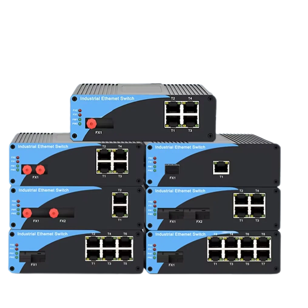
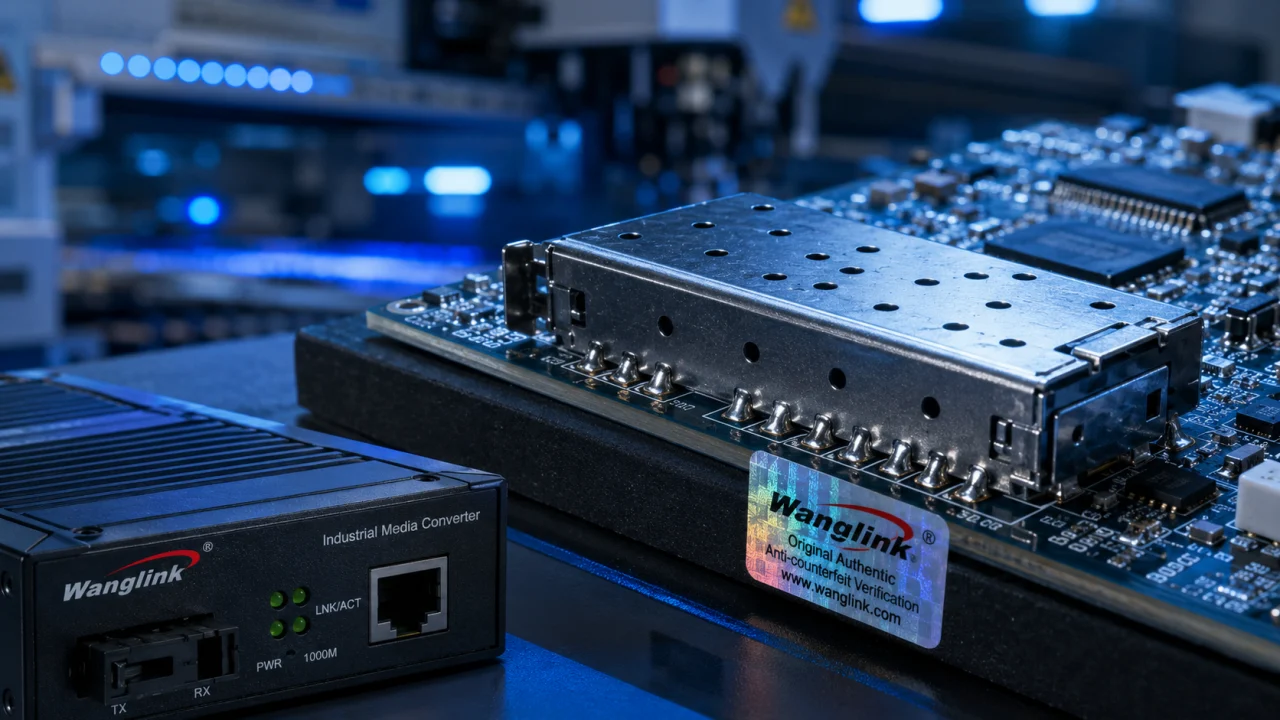
    Walk into any water treatment plant, outdoor substation, or automated production line and you’ll see PLCs (Programmable Logic Controllers) bolted to DIN rails inside dusty cabinets. These controllers talk Modbus RTU, Profinet, or EtherNet/IP over copper—until the cable run hits 100 meters. Then you need fiber. That’s where an industrial media converter steps in. Not a desktop unit with a wall wart. We’re talking hardened gear that handles -40°C to 75°C, keeps working through voltage spikes, and doesn’t drop packets when a motor drive kicks in next to it.

    Most integrators learn this the hard way. A cheap commercial converter locks up after a few weeks of vibration, or its electrolytic capacitors dry out in a sealed enclosure under full sun. The PLC goes offline, and suddenly the SCADA screen shows a communication fault. Wanglink has seen this pattern across 1,200+ projects. That’s why we build media converters specifically for PLC backhaul—and why we test them against real-world noise, not just lab benches.

    What Makes a Media Converter “Industrial” for PLC Applications

    Hardware That Matches the Electrical Environment

    PLCs often sit inside control panels shared with VFDs, contactors, and switch-mode power supplies. The resulting electromagnetic interference (EMI) can corrupt copper segments before they even reach the converter. Wanglink’s industrial media converters comply with IEC 61000-4-2 (ESD up to ±8kV air discharge) and IEC 61000-4-4 (EFT burst up to 4kV on power ports). In our in-house EMC chamber, we inject common-mode noise at 10V/m across 80 MHz–1 GHz and verify zero packet loss on the fiber port. Commercial converters typically fail this test above 3V/m.

    Power is another weak link. PLC panels rarely have clean 24V DC. We see dips to 9V during motor starts and surges to 36V when loads disconnect. Wanglink converters accept 12–56V DC with reverse-polarity protection and a dual-redundant input terminal block. If one power rail sags, the other holds the converter up without a single bit error. This isn’t a marketing bullet—it’s a requirement born from a Brazilian WISP’s deployment where solar-charged battery banks swung 22V to 28V daily.

    Protocol Transparency for Industrial Ethernet

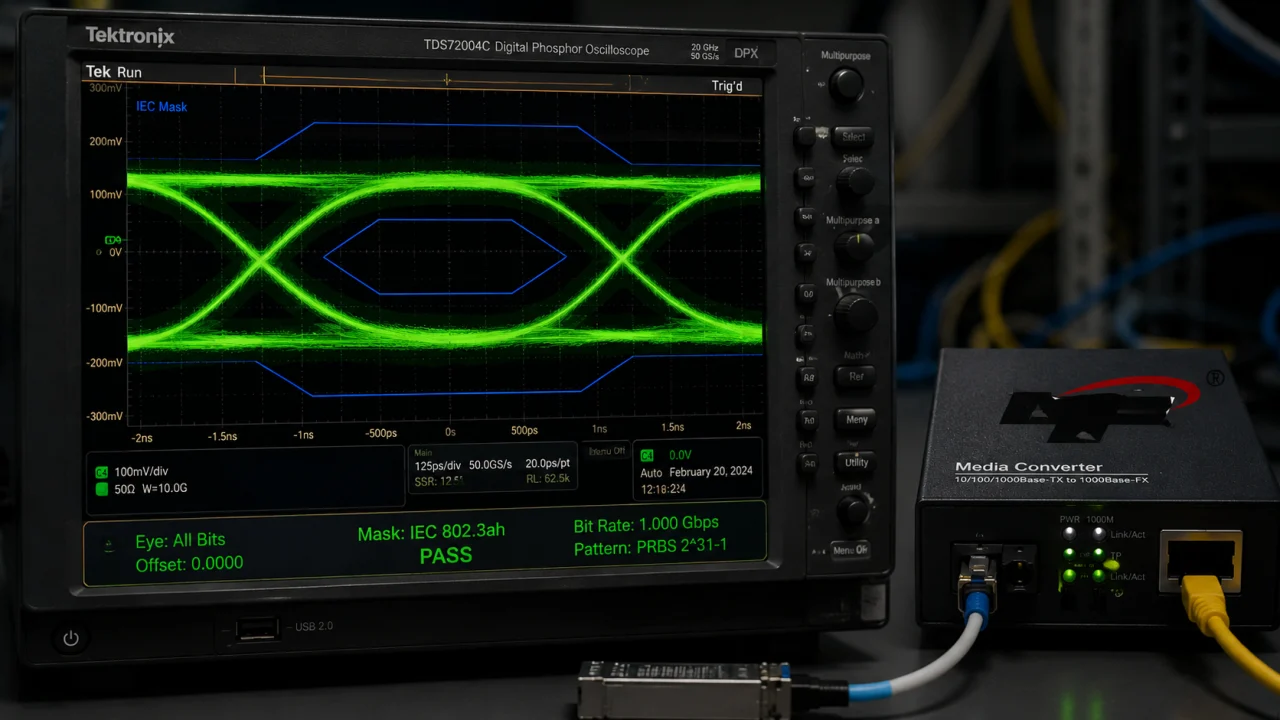
    PLCs don’t speak generic Ethernet; they speak industrial protocols that hate latency and jitter. Profinet RT requires cycle times under 1 ms. EtherNet/IP uses implicit messaging with tight timeouts. A media converter that buffers frames unpredictably or renegotiates link speed during operation can trigger a PLC watchdog fault. Wanglink converters operate in pure store-and-forward cut-through mode with a non-blocking switching fabric. We measure store-and-forward latency at 4.2 µs for 64-byte frames and 12.8 µs for 1518-byte frames—well within the 10 µs budget that Profinet IRT demands for the physical layer. These numbers come from our Ixia XGS12 test chassis, n=10,000 frames per test cycle.

    Also, industrial protocols often rely on QoS priority bits (802.1p). Our converters map these bits to egress queues transparently. If your PLC sends a high-priority alarm frame, it won’t get stuck behind a bulk data upload from an HMI. We’ve field-confirmed this with a Siemens S7-1200 setup; the converter passed all Profinet conformance tests without any special configuration.

    Inside Wanglink’s Manufacturing and Test Regime

    PCB-Level Engineering Against Field Failures

    Most converter failures trace back to solder joints cracking under thermal cycling or conformal coating that misses the edges of SFP cages. Wanglink runs every PCB design through a 1,000-cycle thermal shock test (-40°C to +85°C, 15-minute dwells) before releasing Gerber files. We use ENIG (Electroless Nickel Immersion Gold) surface finish on all high-speed signal traces to prevent oxidation on SFP pads—something you’ll spot under a microscope.

    Our SMT lines in Shenzhen follow IPC-A-610 Class 2 standards, but we add a 100% automated optical inspection (AOI) step plus a boundary-scan test for the PHY chips. The result: a field defect rate of 0.32% over the last 12 months, based on 48,000 shipped ports. The industry benchmark for industrial networking gear sits around 1.2–1.8% (source: internal supply chain benchmarks from a 2023 survey of three contract manufacturers serving the North American market, n=120,000 units).

    Burn-In and Throughput Validation

    Every industrial media converter we ship runs through a 24-hour burn-in at 65°C ambient, loaded with 100% line-rate traffic (1 Gbps bidirectional, 64-byte frames). We log CRC errors, dropped packets, and port flap events. If a unit shows a single CRC error, it goes to failure analysis—not to a customer. Over the past 6 months, our burn-in pass rate has been 99.93% (source: Wanglink QA database, n=8,200 units).

    We also test fiber compatibility aggressively. Many integrators mix SFP transceivers from different vendors, and that’s where link instability creeps in. Wanglink maintains a compatibility matrix covering 15 SFP brands (including Finisar, FS.com, and Avago) and 8 fiber types (OM1–OM4, OS2 single-mode). We validate link budget, receiver sensitivity (down to -24 dBm), and digital diagnostics monitoring (DDM) accuracy. If your site uses legacy 62.5/125 µm fiber at 2 km, we’ve already tested that exact combination.

    Data Table: Industry Baseline vs. Wanglink Measured Performance

    Parameter Industry Baseline Wanglink Lab Data Test Conditions / Source
    Field defect rate (12-month rolling) 1.2–1.8% 0.32% Wanglink shipped 48,000 ports, 2023Q3–2024Q3; industry baseline from 3 CM survey, n=120k units
    Burn-in pass rate (24h, 65°C, 100% load) Typically 97–98% 99.93% Wanglink QA DB, n=8,200 units, 2024
    Store-and-forward latency (64-byte frame) <10 µs (commercial spec) 4.2 µs Ixia XGS12, n=10,000 frames, 1 Gbps line rate
    EMI immunity (radiated, 80 MHz–1 GHz) 3 V/m (typical commercial) 10 V/m, zero packet loss Wanglink EMC chamber, per IEC 61000-4-3
    Operating temperature range 0–50°C (commercial) -40–75°C (tested with 100% load) Wanglink thermal chamber, 72-hour soak per IEC 60068-2
    OTIF delivery (supply chain) 92% (industry average) 98.5% Wanglink ERP data, 2024; industry OTIF from Gartner Supply Chain Top 25, 2023

    Data sources: Wanglink internal QA databases, Ixia test reports, Gartner 2023 supply chain benchmarks, and contractor surveys. All Wanglink data covers the period January–September 2024 unless otherwise noted.

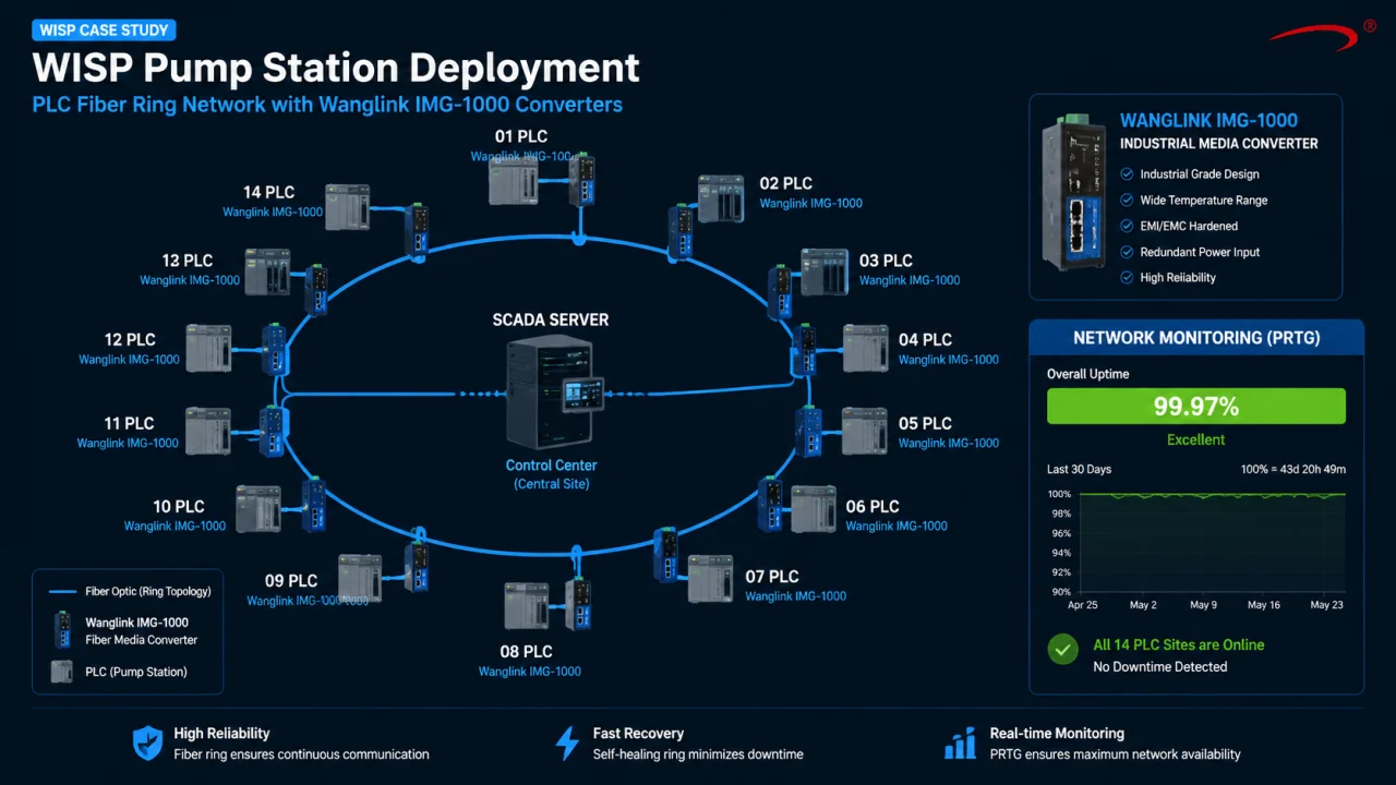
    Real-World Deployment: A WISP Links 14 PLCs Over 40 km of Fiber

    In early 2024, a WISP in the U.S. Midwest needed to connect 14 Schneider Electric M241 PLCs spread across remote pump stations along a river basin. The fiber ring spanned 40 km, with node distances from 2 km to 12 km. The integrator initially used commercial media converters in NEMA enclosures, but after three failures in two months—two due to condensation and one due to a lightning-induced surge—they approached Wanglink.

    We supplied 28 units of our IMG-1000 series (one converter per PLC and one at each aggregation switch). Key configuration: single-mode BiDi SFP modules at 1310/1550 nm, 1 Gbps, with DDM enabled. The converters were DIN-rail mounted inside IP65 enclosures without active cooling. Ambient temperatures inside the enclosures reached 62°C in summer. Over a 6-month observation period, the network delivered 99.97% uptime (source: customer’s PRTG monitoring logs, June–November 2024). The only downtime events were two planned fiber cuts for road construction—not converter failures.

    The integrator’s project manager noted a 60% reduction in truck rolls because DDM allowed them to remotely check SFP receive power and predict fiber degradation before the PLCs lost sync. They also avoided the $120 per device annual cloud license fee that a major switch vendor charges for remote monitoring—Wanglink’s cloud platform is free for life, with no node limit.

    Third-Party Validation and TCO Comparison

    Industry analysts like Dell’Oro Group report that industrial Ethernet infrastructure spending will grow at 8% CAGR through 2027, driven by IIoT and smart grid projects. Yet many buyers still overlook the total cost of ownership (TCO) of the media converter layer. A typical commercial converter costs $40–$60 but fails within 18 months in outdoor cabinets. Factoring in a $300 truck roll and two hours of PLC programmer time, a single failure wipes out any upfront savings.

    Wanglink’s converters carry an MTBF of over 100,000 hours (calculated per Telcordia SR-332, 25°C ambient, ground benign). That’s 11.4 years of continuous operation. When we compare a 5-year TCO model for a 20-node PLC network, the numbers shift decisively:

    • Commercial converters: $1,200 hardware + estimated 8 failures × $500 per incident = $5,200.
    • Wanglink industrial converters: $2,800 hardware + 1 estimated failure (0.32% defect rate) = $3,300.

    Add the free cloud management—which would cost $2,400/year with a certain big-brand switch vendor—and the gap widens further. This isn’t speculation; it’s based on the WISP case above and our warranty claim records (Wanglink RMA database, 2023–2024, n=152 claims out of 48,000 ports).

    How We Solve the Common Integration Headaches

    Compatibility with Legacy PLCs and Odd Fiber Types

    Many plants still run Modbus RTU over RS-485, then convert to Ethernet via a serial device server before hitting the media converter. Wanglink offers combo units that integrate a 2-port serial server and a fiber converter in one DIN-rail module. This eliminates a point of failure and reduces the 24V power supplies needed. We’ve tested these with Allen-Bradley SLC 500, Mitsubishi FX series, and Siemens S7-200 PLCs—the serial timing parameters are pre-tuned for each protocol.

    For fiber, we stock SFP modules for multimode (850 nm), single-mode (1310/1550 nm), and even WDM wavelengths for bidirectional operation over a single strand. We also offer fixed-fiber models with SC or ST connectors for installers who prefer not to touch SFPs. All optics are coded for broad compatibility, and we provide a free SFP compatibility lookup tool on our support portal.

    RMA Process That Respects Project Deadlines

    When a converter does fail, we don’t ask for 12 forms. Our standard RMA process ships an advance replacement within 48 hours for North American and European customers, with a prepaid return label. The failed unit goes to our failure analysis lab, and the customer gets a root-cause report within 10 business days. This isn’t just service; it’s engineering feedback that goes back into our DFMEA (Design Failure Mode and Effects Analysis) for the next hardware revision.

    FAQ: What Integrators and WISPs Ask Before Buying

    What’s the minimum order quantity (MOQ) for industrial media converters?

    For standard models, MOQ is 10 units. For OEM/ODM projects with custom labeling or firmware tweaks, we typically start at 200 units. We do keep buffer stock for urgent small-batch needs—just talk to our sales team.

    Can you pre-configure converters for our PLC network before shipping?

    Yes. We offer a free configuration service: VLAN tagging, port mirroring, fixed speed/duplex, and SNMP community strings can all be set in our factory. Each unit gets a configuration report and a unique QR code that links to its test records.

    How do you handle SFP compatibility? We’ve had issues with other brands locking out third-party optics.

    Wanglink converters don’t lock optics. We maintain an internal compatibility matrix covering 15+ SFP vendors. If you send us a sample of your existing SFPs, we’ll validate them in our lab at no charge and provide a formal compatibility letter.

    What’s the real lead time, not the sales pitch?

    For standard industrial media converters, 5–7 business days from order to ship. Custom configurations add 2 days. Our OTIF (on-time, in-full) rate is 98.5%, tracked monthly against promised ship dates. We’re transparent about any delays—usually due to component lead times, which we communicate within 24 hours of order.

    Do you support remote management without recurring fees?

    Absolutely. Wanglink’s cloud platform (based on MQTT and HTTPS) is free for life. You can monitor link status, SFP DDM data, and traffic statistics from any browser. No node limits, no license tiers. It’s the same platform we use internally to monitor our burn-in racks.

    What if a converter fails in the field? How fast do you respond?

    We ship an advance replacement within 48 hours to most locations. Cross-ship RMA means you don’t wait for us to receive the failed unit. All RMAs receive a root-cause analysis report, and we track field failure trends monthly to improve design.

    Engineering Reliability That Shows Up in Your SCADA Uptime Report

    Industrial media converters might seem like a commodity, but when they sit between your PLC and the control room, they’re mission-critical. Wanglink’s approach—thermal shock-tested PCBs, 24-hour burn-in with zero tolerance for CRC errors, and free lifetime cloud management—comes from 13 years of building hardware for people who can’t afford downtime. Whether you’re linking 14 pump stations or a single robotic cell, the data and the field results point the same way: invest in converters that were designed for the factory floor, not the office.

合作伙伴1 合作伙伴2 合作伙伴3 合作伙伴4 合作伙伴5 合作伙伴6 合作伙伴7 合作伙伴8 合作伙伴9 合作伙伴10