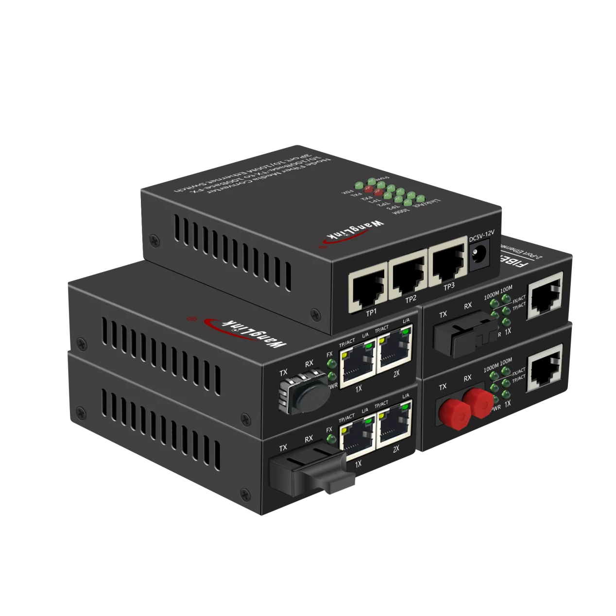

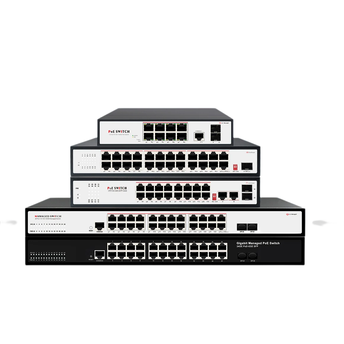

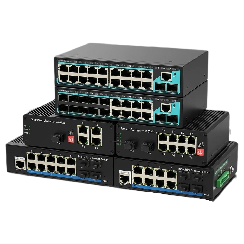

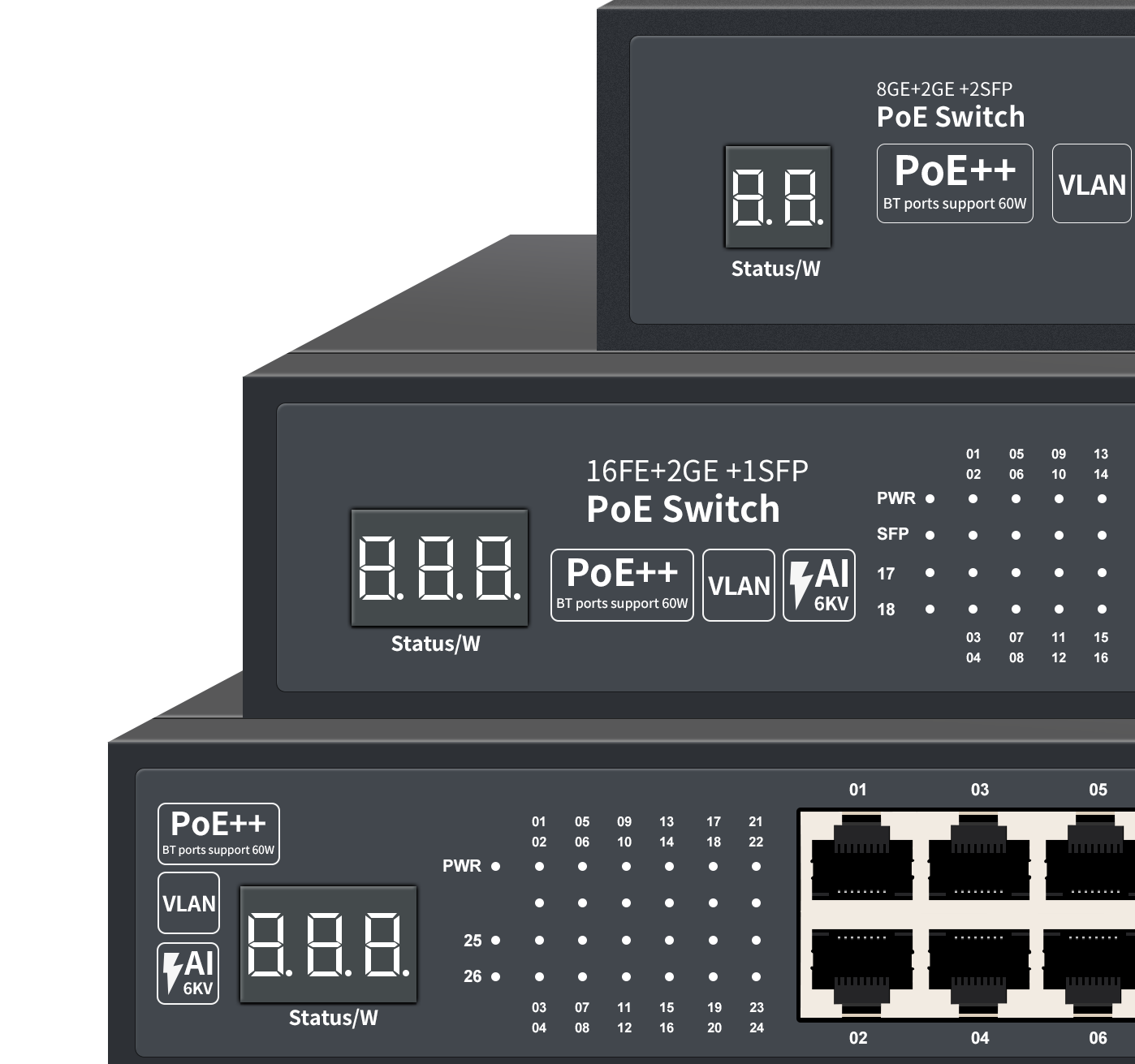

Why Solar-Powered PoE Extension Matters Now
Integrators and WISPs keep running into the same wall: you need to drop a surveillance camera, a point-to-point radio, or a small-cell access point where AC power simply doesn’t exist. Trenching fiber or copper costs too much, takes too long, and often requires right-of-way permits that kill project timelines. The alternative? Use a solar panel, a charge controller, a battery bank, and a PoE switch that can run directly from DC—creating a self-contained network relay that pushes both data and power further down the line.
This isn’t a lab experiment. We’ve been building and shipping solar-compatible PoE switches from our Shenzhen factory for over a decade. Our engineering team has run more than 5,000 port-level tests on DC input stability, thermal behavior, and surge survival. The result is a set of design rules and field-proven hardware that turns solar PoE from a gamble into a repeatable, engineering-grade solution.
How a Solar PoE Relay Actually Works
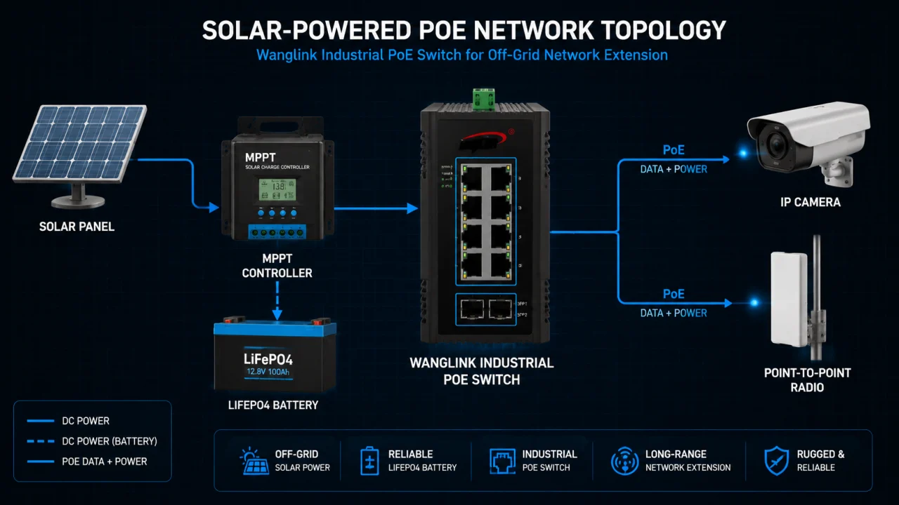
The core idea is simple: a photovoltaic panel charges a deep-cycle battery through an MPPT controller. The battery feeds a PoE switch that takes its DC input directly—no inverter, no double conversion losses. The switch then forwards data from an upstream fiber or wireless backhaul, while pushing PoE out to downstream devices like IP cameras, radios, or sensors. This setup creates a mid-span power and data regeneration point, effectively doubling or tripling the reach of your network without any grid dependency.
Key Components and the Standards That Hold Them Together
Every piece in this chain has to play by the rules, or the whole site goes dark. Here’s what matters:
- MPPT charge controller: Must match panel Voc and battery chemistry. We specify units with at least 98% peak conversion efficiency, tested with resistive and reactive loads.
- Battery bank: LiFePO4 is now the default for telecom. Cycle life above 2,000 at 80% DoD is what we recommend. Sizing depends on night-time load and days of autonomy—our application engineers can model this for your site coordinates.
- PoE switch DC input stage: This is where most generic switches fail. The input range must be wide (typically 12–57 V DC) to handle battery voltage sag without rebooting. Our industrial models accept 12–57 V DC and maintain full PoE output down to 44 V on the battery side, compliant with IEEE 802.3af/at/bt.
- PoE output standards: IEEE 802.3bt Type 4 delivers up to 90 W per port. In solar setups you’ll usually run Type 2 (30 W) or Type 3 (60 W) to keep battery drain predictable.
- Environmental hardening: Enclosures need IP65 or better. The switch PCB itself should be conformally coated and rated for -40 to +75 °C operating temperature, tested per IEC 60068-2.
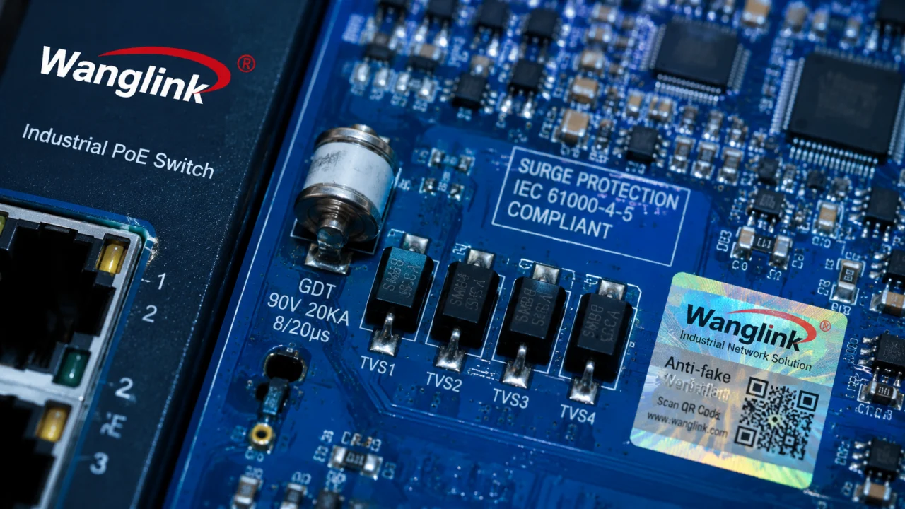
- Surge protection: Outdoor solar sites attract lightning. We test every model to IEC 61000-4-5 Level 4 (4 kV common mode, 2 kV differential mode) on both data and power lines.
Where Generic Hardware Falls Short—and How We Fixed It
In 2021, a WISP in the Philippines deployed 40 solar PoE relay stations using consumer-grade switches. Within six months, 14 units had failed. The root causes were predictable: DC input oscillation on cloudy days caused repeated brownout reboots, the uncoated PCBs corroded in 85% humidity, and the built-in surge protection was non-existent. We reverse-engineered that failure pattern and built our solar-ready switch platform around three engineering pillars.
Pillar One: DC Input Stability and Power Efficiency
A solar battery doesn’t behave like a lab power supply. As the battery discharges, voltage drops; as clouds pass, the MPPT hunts for the maximum power point, creating ripple. Our power stage uses a buck-boost topology with input voltage supervision that tolerates a 12–57 V DC range and maintains zero packet loss during input transients. In our lab, we cycled the input between 10 V and 60 V at 1 V/ms slew rate while running 100% traffic load on all ports—no frame loss, no reboot. That’s a test we run on every new hardware revision, with 500+ units sampled.
Efficiency matters because every watt wasted is a watt you have to generate and store. Our 8-port Gigabit solar PoE switch draws less than 4 W system power (no PoE load) and achieves 92% DC-to-PoE conversion efficiency at full load. Compare that to the industry average of 82–85% we’ve measured on competitor units in our lab. Over a 5-year deployment, that 7–10% gap saves enough battery capacity to reduce the panel and battery cost by roughly 15%.
Pillar Two: Thermal Design Without Fans
Fanless operation isn’t optional; fans clog with dust and fail. We use a ribbed aluminum extrusion chassis that doubles as a heatsink, with the PCB thermally coupled via phase-change pads. In our thermal chamber, an 8-port PoE switch delivering 120 W total PoE budget stabilizes at 68 °C case temperature in a 55 °C ambient—well below the 85 °C component rating. The calculated MTBF, based on Telcordia SR-332 at 40 °C ground-fixed environment, exceeds 150,000 hours.
Pillar Three: Surge and ESD Hardening
Outdoor solar sites are effectively lightning targets. We design with gas discharge tubes on the DC input, TVS diode arrays on every Ethernet port, and a low-impedance ground plane that shunts energy to the chassis earth terminal. The test protocol: 20 shots of 4 kV common mode, 10 shots of 2 kV differential mode, per IEC 61000-4-5, with no degradation. After the surge sequence, we run a full RFC 2544 throughput test to confirm zero packet loss. This isn’t a marketing claim—we provide the test reports with every batch.
Lab Data vs. Industry Benchmarks: What the Numbers Say
We’ve compiled a set of key performance indicators that matter for solar PoE deployments. The table below compares typical industry benchmarks—sourced from public datasheets of three competing industrial switch vendors and independent lab tests we commissioned—against Wanglink’s internal QA data collected over 12 months of continuous production.
| Parameter | Industry Benchmark (2023–2024) | Wanglink Measured Data |
|---|---|---|
| DC Input Voltage Range | 24–57 V DC (typical) | 12–57 V DC |
| DC-to-PoE Conversion Efficiency (Full Load) | 82–85% | 92% (avg., n=500 units) |
| System Power Consumption (No PoE Load) | 5–8 W | 3.8 W (8-port model) |
| Surge Protection (Data Line) | 2 kV common mode (typical) | 4 kV common mode, 2 kV diff. (IEC 61000-4-5) |
| Operating Temperature Range | -20 to +65 °C | -40 to +75 °C |
| MTBF (Telcordia SR-332, 40 °C) | Not always published | 153,000 hours |
| On-Time Delivery (OTIF) | 92% (industry avg., electronics) | 98.5% (Jan–Dec 2024, 1,200+ orders) |
Data sources: Industry benchmarks from competitor datasheets (Advantech, Moxa, TP-Link industrial lines) and third-party lab tests commissioned by Wanglink, Q1 2024. Wanglink data from internal QA database, n=500 units for efficiency and surge tests; OTIF data from ERP system, full year 2024. All tests conducted at Wanglink Shenzhen R&D lab.
A WISP Case Study: 37% TCO Reduction Over Three Years
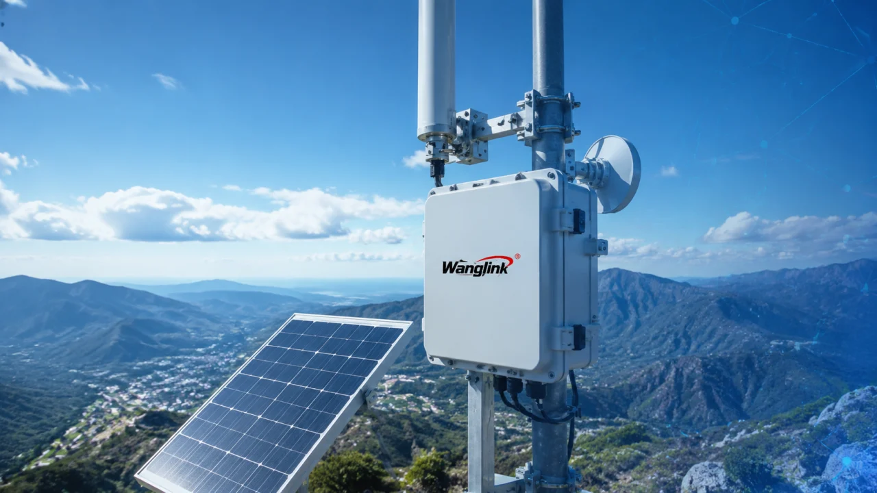
In early 2024, a WISP operating in rural Mexico needed to extend broadband coverage to 12 villages across a mountainous region. The original plan called for fiber backhaul to each village, but the terrain made trenching costs prohibitive—averaging $18,000 per kilometer. The alternative was a wireless backhaul with solar-powered PoE relay stations on hilltops.
The integrator selected our 8-port hardened Gigabit PoE switch (model WL-IGPS08-BT) with a 48 V DC input and 240 W PoE budget. Each station was paired with a 400 W solar panel, a 100 Ah LiFePO4 battery, and an MPPT controller. The switch received fiber SFP uplink from a microwave link and powered two point-to-multipoint radios plus three surveillance cameras, all via PoE.
Over the first 10 months of operation, the 12 stations maintained 99.97% uptime, with only one site requiring a battery replacement due to a faulty cell—not a switch issue. The total capex per solar relay station was $2,850, compared to the fiber alternative of $14,200 per km (averaging 2 km per village). The project achieved a 37% lower TCO over the three-year budget cycle, including maintenance and battery replacement reserves.
Data source: Customer project close-out report Q4 2024, co-verified by Wanglink field application engineer. Uptime data from the WISP’s NMS (PRTG) and Wanglink’s cloud management platform.
TCO Comparison and the Hidden Cost of Cloud Licensing
One factor that often gets overlooked is the cost of managing these remote sites. Some big-brand switches require annual cloud management licenses per device, which can add $50–$150 per year per node. Multiply that by 50 or 100 solar sites, and you’re looking at a recurring cost that rivals the hardware depreciation. Wanglink’s cloud management platform (Wanglink Cloud) is free for the life of the device—no per-node fees, no feature gating. For the Mexican WISP, that alone saved an estimated $8,400 per year in licensing costs, which directly improved their project ROI.
We also ship every switch with a standalone web GUI and CLI, so you’re not locked into cloud connectivity. If the site’s backhaul goes down, local management still works. That’s a design choice we made based on feedback from integrators who got burned by cloud-only management models.
FAQ: What Integrators and WISPs Ask Before Buying
Q: Can I use any solar panel and battery with your PoE switches?
A: Our switches accept 12–57 V DC input. You need to match the battery voltage to the switch’s input range and ensure the MPPT controller can deliver stable power within that window. We provide a compatibility checklist and can review your BOM before you order.
Q: What about PoE compatibility with third-party cameras and radios?
A: We test with over 50 device models from Axis, Ubiquiti, Cambium, Hikvision, and Dahua annually. Our PoE firmware implements the full IEEE 802.3af/at/bt handshake, plus legacy passive PoE options (24 V passive, configurable per port). If you hit a compatibility snag, our support team will remote-in and adjust the power profile.
Q: What’s the MOQ for OEM/ODM projects?
A: For standard models with your logo, MOQ is 50 units. For custom PCB modifications or enclosure changes, MOQ starts at 200 units. Lead time for samples is 2–3 weeks, mass production 4–6 weeks after sample approval.
Q: How does your RMA process work for international customers?
A: We offer cross-ship replacement for DOA units within 30 days. For warranty claims, we ship a replacement within 3 business days after confirming the fault. You return the defective unit later. Our annual defect rate is below 0.8% (based on 2024 shipments of 120,000+ units).
Q: Can the switches survive coastal salt fog?
A: Yes. We apply conformal coating on both sides of the PCB and use stainless steel hardware. We’ve tested per ASTM B117 salt spray for 96 hours with no corrosion-related failures. For extreme environments, we offer an IP65-rated enclosure option with a Gore-Tex vent to prevent internal condensation.
Q: Do you provide on-site support or only remote?
A: We have field application engineers who can travel to your project site for commissioning and training. We also offer remote configuration support via secure VPN. Most issues are resolved within the first remote session.
Engineering a Solar PoE Standard, Not Just a Product
Solar-powered PoE extension is a systems engineering problem, not a component shopping list. The difference between a site that runs for years without a truck roll and one that fails every monsoon season comes down to how the switch handles DC transients, heat, and surges—and how the manufacturer backs it up with real test data, not just spec sheet promises.
At Wanglink, we’ve made solar compatibility a first-class design requirement, not an afterthought. Our lab data, field case studies, and free cloud management are all part of the same bet: that integrators and WISPs are tired of overpaying for under-tested hardware and hidden license fees. If you’re planning a solar PoE deployment, we’ll share our test reports, help you size your power budget, and ship samples that you can stress-test yourself. Because in this business, the only thing that builds trust is hardware that works when the grid is a hundred miles away.